Micro-mechanical component

a micro-mechanical and component technology, applied in the direction of micro-structural devices, fluid speed measurement, instruments, etc., can solve the problems of low cost, low change in properties, in particular quality, and achieve the effect of fewer changes in properties

Active Publication Date: 2018-02-15
ROBERT BOSCH GMBH
View PDF2 Cites 0 Cited by
  • Summary
  • Abstract
  • Description
  • Claims
  • Application Information

AI Technical Summary

Benefits of technology

[0005]It is an object of the present invention to provide a micromechanical component that exhibits fewer changes in the properties, in particular in the quality of the micromechanical component over the service life of the micromechanical component, and to do so is an uncomplicated and economical manner.

Problems solved by technology

In contrast to the related art, a change in the properties, in particular in the quality of the micromechanical component across the service life of the micromechanical component, is kept low in an uncomplicated and cost-effective manner.

Method used


Image

  • Micro-mechanical component
  • Micro-mechanical component
  • Micro-mechanical component

Examples


Embodiment Construction

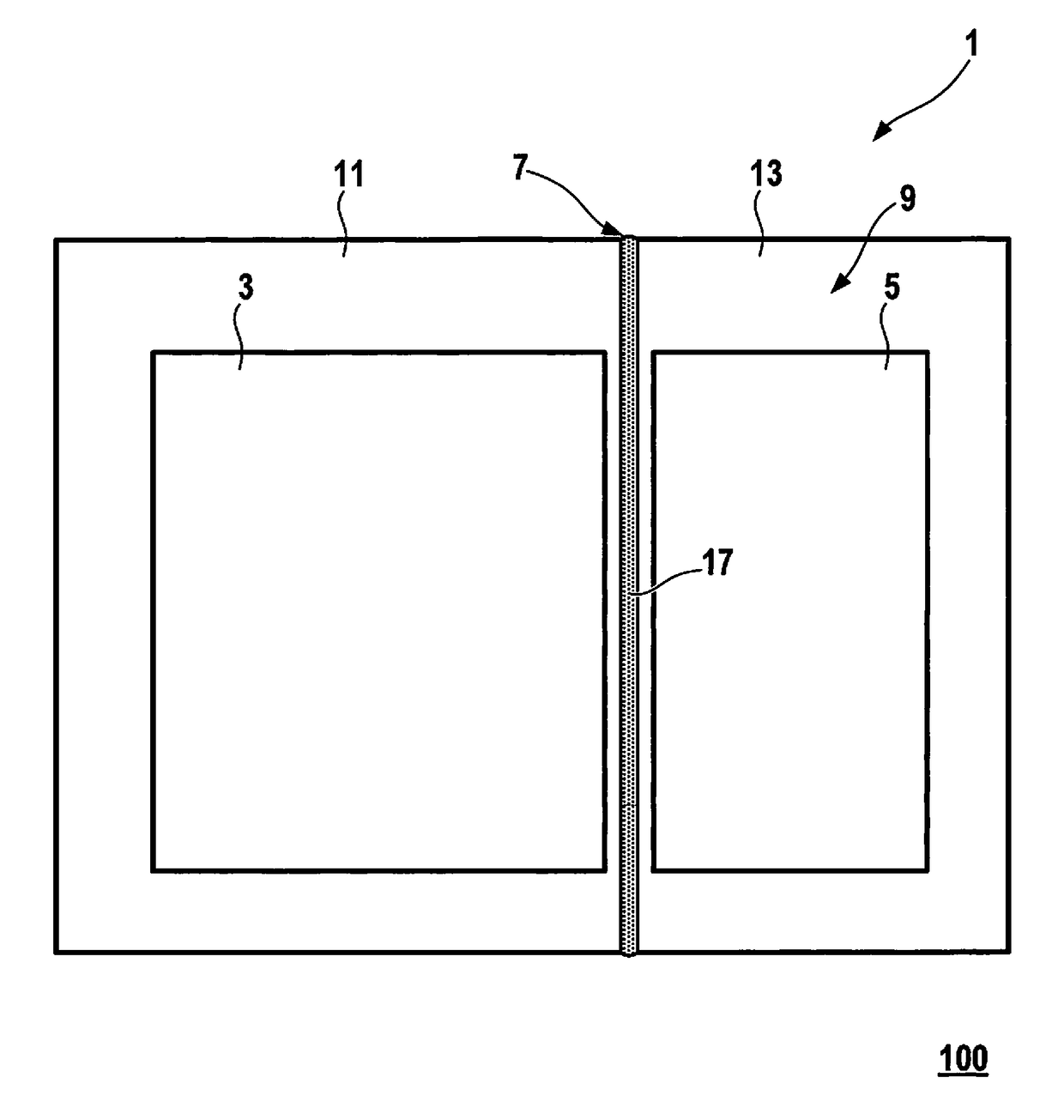
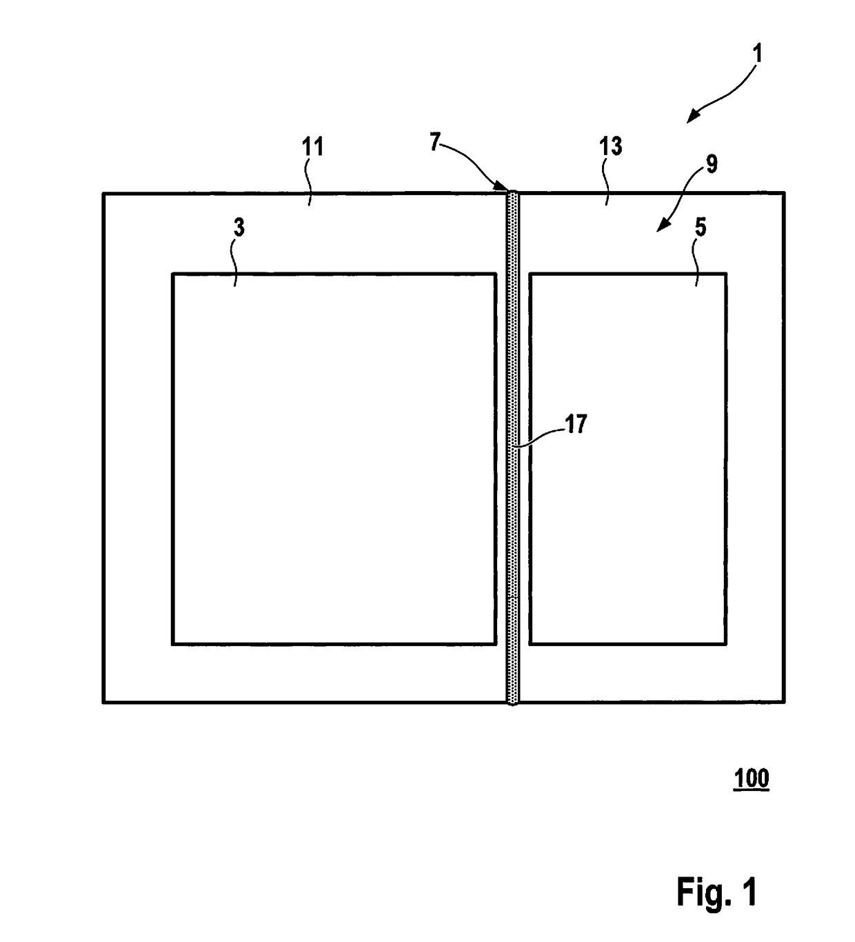
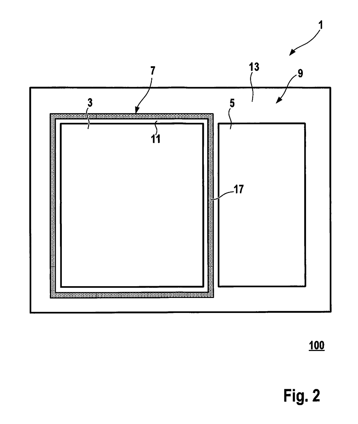
[0032]FIG. 1 shows a schematic representation of a micromechanical component 1 according to an exemplary specific embodiment of the present invention, micromechanical component 1 having a main extension plane 100. Main extension plane 100 may be a main extension plane of a substrate 19 of micromechanical component 1. Micromechanical component 1 encloses a first cavern 3 and a second cavern 5, and a first pressure prevails in first cavern 3 and a second pressure prevails in second cavern 5. Especially preferably, the first pressure is lower than the second pressure. A first sensor unit for the rate-of-rotation measurement, i.e. a rate-of-rotation sensor, is disposed in first cavern 3, and a second sensor unit for the acceleration measurement, i.e. an acceleration sensor, is disposed in second cavern 5.

[0033]Micromechanical component 1 preferably encompasses a base structure, which includes substrate 19, and a cap structure. The base structure is connected to the cap structure, especi...


PUM


Abstract

A micromechanical component having a main extension plane is provided; the micromechanical component encloses a first cavern and a second cavern, and a first pressure prevails in the first cavern while a second pressure prevails in the second cavern, and a first layer of the micromechanical component, which extends essentially parallel to the main extension plane, projects into a second layer of the micromechanical component, which extends essentially parallel to the main extension plane, between the first cavern and the second cavern, essentially in a perpendicular direction to the main extension plane.

Description

RELATED APPLICATION INFORMATION[0001]The present application claims priority to and the benefit of German patent application no. 10 2016 214 966.0, which was filed in Germany on Aug. 11, 2016, the disclosure which is incorporated herein by reference.FIELD OF THE INVENTION[0002]The present invention is based on a micromechanical component.BACKGROUND INFORMATION[0003]A micromechanical component of this type is generally known. For example, the document U.S. Pat. No. 8,546,928 B2 describes a micromechanical component which has two caverns; here, both a relatively low internal cavern pressure for a rate-of-rotation sensor of the micromechanical component and a relatively high internal cavern pressure for an acceleration sensor of the micromechanical component are provided on the same chip. The internal cavern pressure for the rate-of-rotation sensor is kept at a relatively low level with the aid of a getter situated inside the cavern.[0004]However, in the course of the miniaturization o...

Claims


Application Information

Patent Timeline
Patent Type & Authority Applications(United States)
IPC IPC(8): B81B7/00
CPCB81B7/0038B81B7/02G01P15/00G01P3/00B81C1/00285B81B7/0041B81B2201/0235B81B2203/0315B81B2201/025G01P15/0802G01C19/5783
Inventor BREITLING, ACHIMSCHWENK, CHRISTOFKUEPPERS, HARTMUTSCHITTENHELM, NICOLESCHMITZ, VOLKER
Owner ROBERT BOSCH GMBH
Why Eureka
Try Eureka