Organic EL devices

a technology of organic el and devices, which is applied in the direction of discharge tube/lamp details, discharge tube luminescnet screens, natural mineral layered products, etc., can solve the problems of low luminescent efficiency, low colour reproducibility, and low luminescent efficiency, and achieves superior chromaticity (whiteness), less changes in chromaticity (whiteness), and superior chromaticity

Inactive Publication Date: 2010-12-21
TOYOTA IND CORP
View PDF19 Cites 6 Cited by
  • Summary
  • Abstract
  • Description
  • Claims
  • Application Information

AI Technical Summary

Benefits of technology

[0047]Compared to conventional organic EL devices, the first, second, and third organic EL devices of the present invention can provide advantages such as superior chromaticity (whiteness), superior colour reproducibility, less changes in chromaticity (whiteness) upon measuring lifetime, etc., and improved luminescent efficiency and lifetime.

Problems solved by technology

However, organic EL devices having only two luminescent layers have a problem of low colour reproducibility.
Even if organic EL devices have three luminescent layers, even if a blue luminescent layer, a green luminescent layer, and a red luminescent layer are sequentially laminated on the anode, and also even if a red luminescent layer, a green luminescent layer, and a blue luminescent layer are sequentially laminated on the anode, there has been a problem of low luminescent efficiency.
Further, even if a carrier-transporting buffer layer is provided between luminescent layers of such organic EL devices, it is difficult to obtain practically satisfactory chromaticity, colour reproducibility, luminescent efficiency, long lifetime, etc.

Method used


Image

  • Organic EL devices
  • Organic EL devices

Examples


example 1

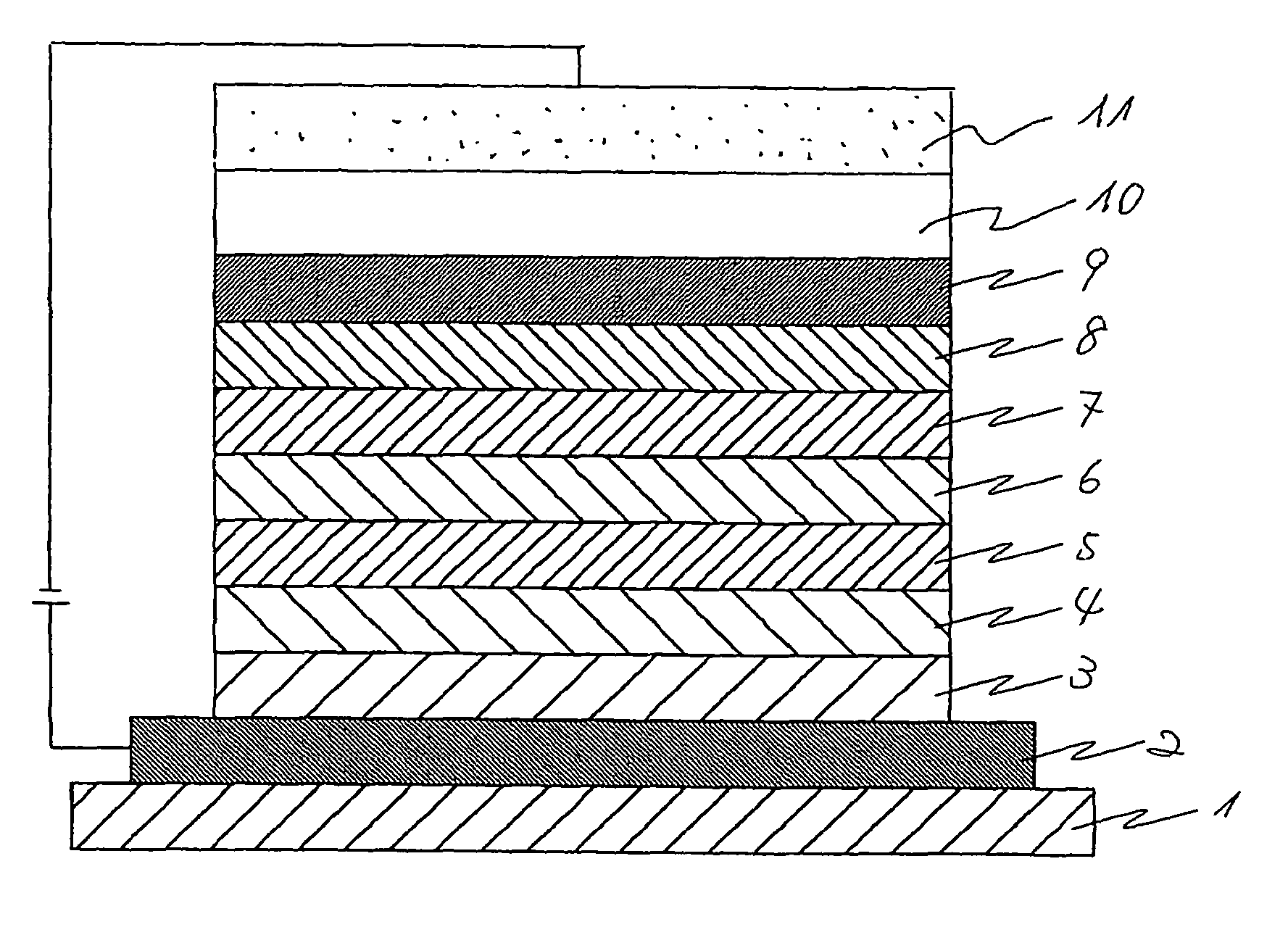
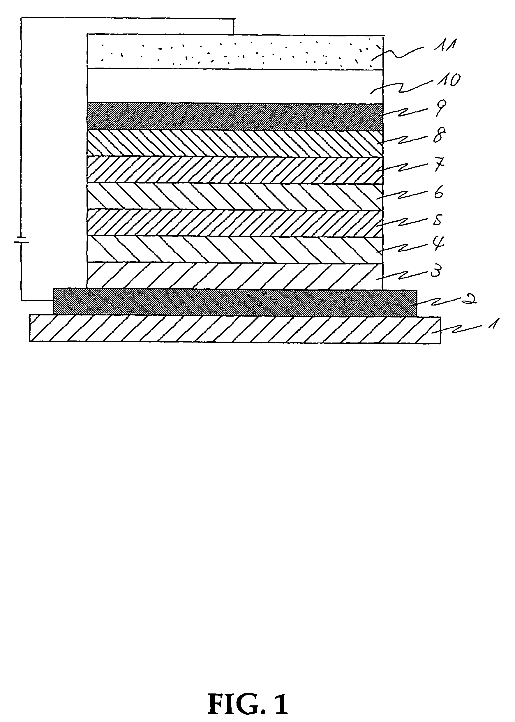
[0166]A transparent glass, that is a substrate, on one of whose surfaces an anode made of an ITO layer of 110 nm film thickness had been formed was prepared, and washed with an alkali and then with pure water, dried, and then washed with UV-ozone.

[0167]On the anode on thus washed glass, using a vacuum-vapor-deposition apparatus (a carbon crucible, at a vapor-deposition speed of 0.1 nm / s, in vacuo around 5.0×10⁻⁵ Pa), an HI layer of 10 nm film thickness was prepared to be a hole-injecting layer.

[0168]On the hole-injecting layer, using a vacuum-vapor-deposition apparatus (a carbon crucible, at a vapor-deposition speed of 0.1 nm / s, in vacuo around 5.0×10⁻⁵ Pa), an HT layer of 50 nm film thickness was prepared to be a hole-transporting layer.

[0169]On the hole-transporting layer, using a vacuum-vapor-deposition apparatus (a carbon crucible, in vacuo around 5.0×10⁻⁵ Pa), a layer of 5 nm film thickness was prepared by co-vapor-deposition of a host material HT and a red dopant RD to be a re...

examples 2-14

[0176]Similar to example 1, examples 2-14 involve in their blue and green luminescent layers at least one common derivative and were prepared similarly to example 1 except that their blue and green luminescent layers were changed as shown in table 1 below.

[0177]That is, examples 2-4 involve as host materials of the blue and green luminescent layers a common derivative BH1, which is a distyryl arylene derivative, similar to example 1. Examples 5-7 involve as dopants of the blue and green luminescent layers common derivatives BD1 and GD2 (a distyrylamine derivative), respectively. Examples 8 and 9 involve as host materials of the blue and green luminescent layers common derivatives BH2 and GH1 (a metal-quinolinolate complex), respectively. Example 10 involves as host materials of the blue and green luminescent layers a common derivative BH5 a carbazole derivative). Example 11 involves as host materials of the blue and green luminescent layers a common derivative BH3 (an anthracene der...

example 15

[0179]Example 15 was prepared similarly to example 1 except that a blocking layer of 3 nm film thickness of HT vapor-deposited was provided between the blue and red luminescent layers. Example 15 also involved as host materials of the blue and green luminescent layers a common derivative BH1 (a distyryl arylene derivative).


PUM

PropertyMeasurementUnit
transparencyaaaaaaaaaa
roughnessaaaaaaaaaa
electric resistanceaaaaaaaaaa

Abstract

The present organic EL devices have at least one luminescent layer and a cathode sequentially provided on their anode, which luminescent layer contains an electron-transporting material, a hole-transporting material, and a luminescent dopant. Preferably, an electron-transporting layer is further provided between the luminescent layer and the cathode. According to the present invention, organic EL devices can be provided giving improved whiteness, colour reproducibility, luminescent efficiency, and lifetime compared to conventional ones.

Description

[0001]This application claims the benefit under 35 U.S.C §119 (a)-(d) or 365(b) of Japanese Patent Application No. JP 2004-162042, filed on May 31, 2004.TECHNICAL FIELD[0002]The present invention relates to organic EL devices having on their anode at least one luminescent layer and a cathode sequentially laminated.BACKGROUND ART[0003]Conventionally, organic EL devices have been known which have luminescent layer(s), containing organic luminescent materials, provided between opposing electrodes (an anode and a cathode) wherein the luminescent layer(s) generate(s) light (electro-luminescence, EL) by passing the electric current between these electrodes. Amongst such organic EL devices, JP2000-68057A discloses organic EL devices having two luminescent layers laminated on their anode.[0004]JP10-3990A discloses organic EL devices having a blue luminescent layer, a green luminescent layer, a red luminescent layer, and a cathode sequentially laminated on their anode.[0005]JP2002-175879A di...

Claims


Application Information

Patent Timeline
Patent Type & Authority Patents(United States)
IPC IPC(8): H05B33/14H01L51/00H01L51/50H05B33/22
CPCC09K11/06H01L51/504H01L51/0071H01L51/0072H01L51/0074H01L51/5012H01L51/5044H01L51/5048H01L51/5096H10K85/6576H10K85/6572H10K85/657H10K50/131H10K50/13H10K50/12H10K50/14H10K50/11H10K50/18H05B33/14
Inventor NAGARA, YOSHIAKIYAMAMOTO, ICHIROMORI, KENJIMURASAKI, TAKANORI
Owner TOYOTA IND CORP
Why Eureka
Try Eureka