

Clamping device for continuous adjustment of a display stand
- Summary
- Abstract
- Description
- Claims
- Application Information
AI Technical Summary
Benefits of technology
Problems solved by technology
Method used
Image

Examples
first embodiment
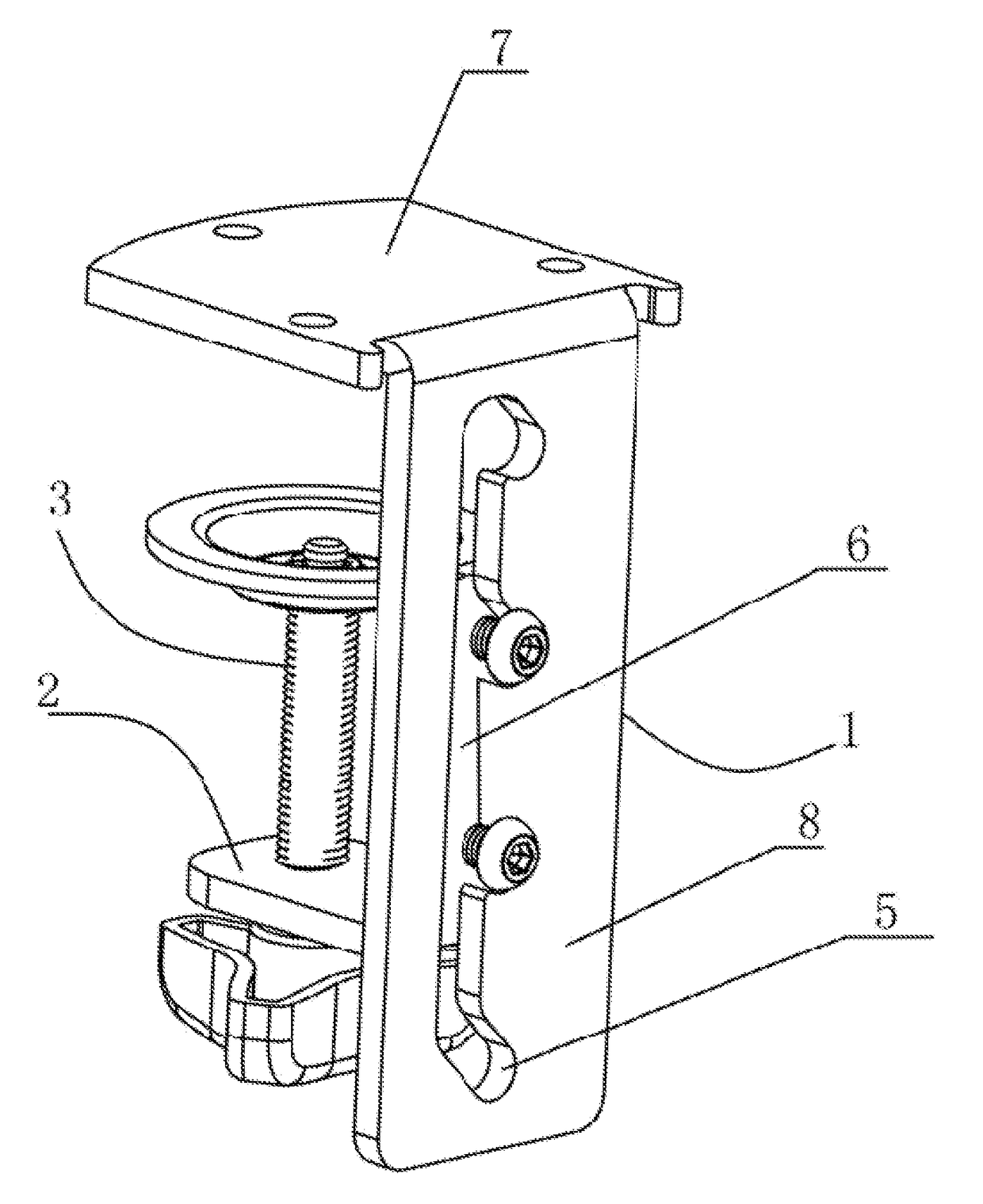
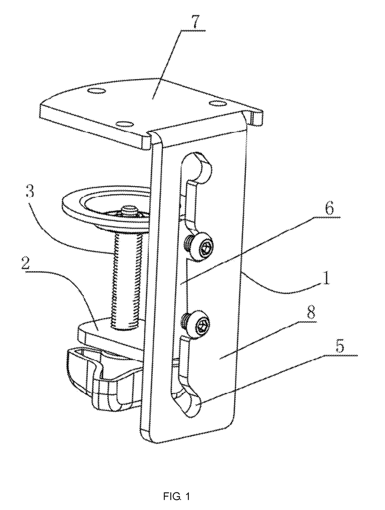
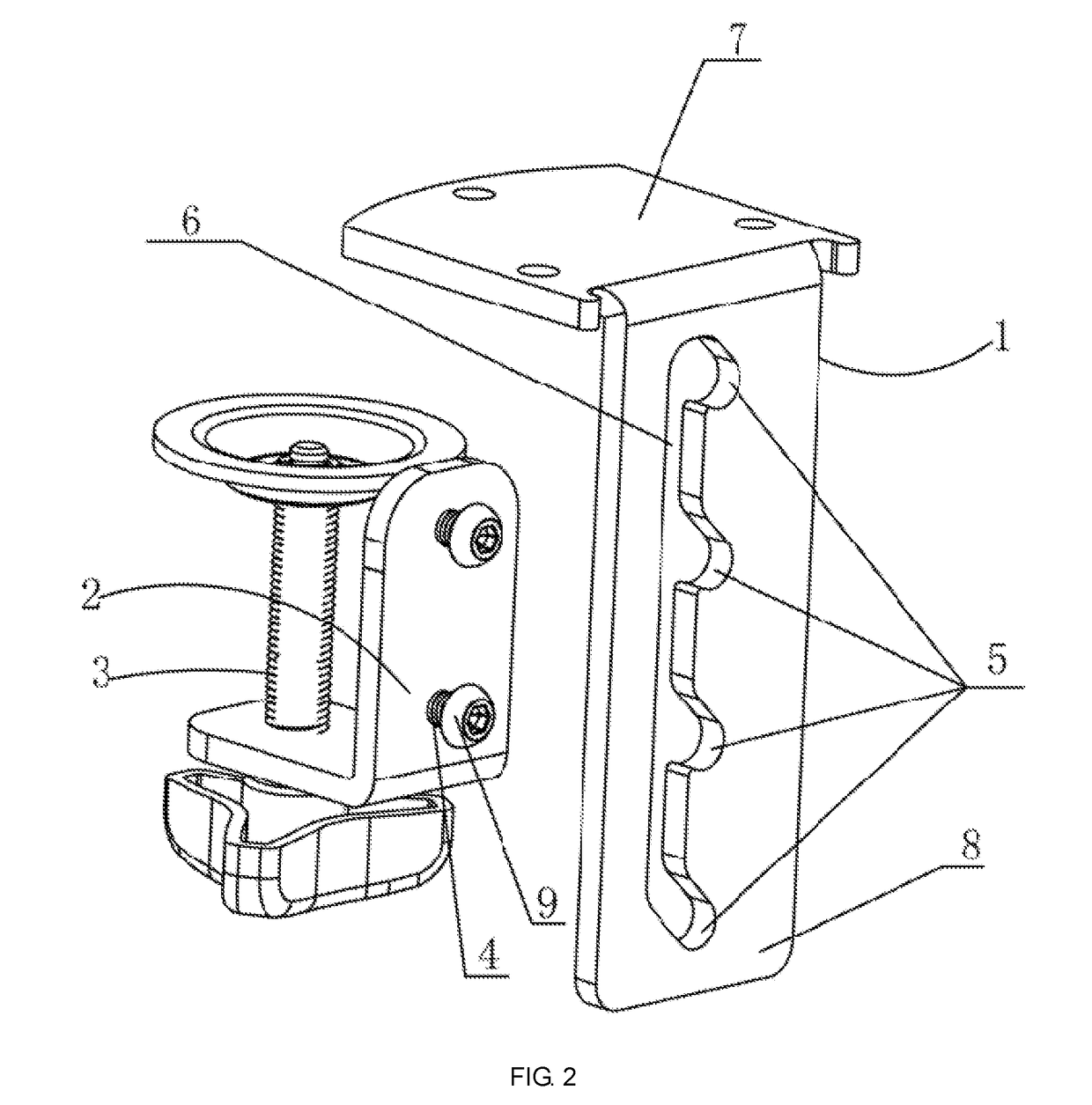
[0028]As shown in FIG. 1-3, a clamping device comprises a holder 1, a connector 2 and a fastening screw 3 screwed to the connector 2 to fasten to a table board. The holder 1 comprises an upper pressing board 7 and a side board 8. A gap is formed between the top of the fastening screw 3 and the bottom of the upper pressing board 7. The connector 2 is connected to the side board 8. At least one connecting column 4 is provided on the connector 2. A plurality of connecting holes 5 are provided on the side board 8 along a vertical direction to receive the at least one connecting column 4. The connecting column 4 connects the connector 2 to the side board 8 through the plurality of connecting holes 5. The connecting column 4 comprises a limiting cap 9 on an extruding end of the connecting column 4 to prevent falling of the connecting column 4 off the plurality of connecting holes 5. The side board 8 further comprises at least one channel 6 to connect at least two connecting holes 5 on di...
second embodiment
[0030]As shown in FIG. 4-6, a clamping device comprises a holder 1, a connector 2 and a fastening screw 3 screwed to the connector 2 to fasten to a table board. The holder 1 comprises an upper pressing board 7 and a side board 8. A gap is formed between the top of the fastening screw 3 and the bottom of the upper pressing board 7. The connector 2 is connected to the side board 8. At least one connecting column 4 is provided on the connector 2. A plurality of connecting holes 5 are provided on the side board 8 along a vertical direction to receive the at least one connecting column 4. The connecting column 4 connects the connector 2 to the side board 8 through the plurality of connecting holes 5. The connecting column 4 comprises a limiting cap 9 on an extruding end of the connecting column 4 to prevent falling of the connecting column 4 off the plurality of connecting holes 5. The side board 8 further comprises at least one channel 6 to connect at least two connecting holes 5 on di...
fourth embodiment
[0032]As shown in FIG. 7-12, the connector 2 of a clamping device according to a third and a fourth embodiment comprises two protruding connecting columns arranged on the same vertical position along the connector. The side board 8 comprises two channels 6 which are parallel with each other and extend in the vertical direction of the side board 8. The plurality of connecting holes 5 comprise at least two pairs of connecting holes arranged along the channels 6. An interval between the connecting holes 5 of each pair is constant. The two connecting holes 5 of each pair are arranged on the same side of the channels 6. The two connecting holes 5 of each pair are connected to the two channels 6 respectively. The two connecting columns 4 are in clearance fit within one pair of connecting holes 5.
[0033]When adjusting the height of the connector relative to the side board of the holder with the clamping device for continuous adjustment of a display stand, the user would not need to disassem...
PUM
 Abstract
Description
Claims
Application Information