Load detecting device for vehicle seat

Inactive Publication Date: 2008-01-10
AISIN SEIKI KK +1
View PDF19 Cites 2 Cited by
  • Summary
  • Abstract
  • Description
  • Claims
  • Application Information

AI Technical Summary

Benefits of technology

[0007] According to an aspect of the present invention, a load detecting device for a vehicle seat includes a supporting base adapted to be mounted on a floor of the vehicle, a plurality of load sensors arranged along a forward and backward direction of a seat for the vehicle on the supporting base, each of the load sensors including a load input portion applied with load, a deflection portion deflecting by a load transmitted from the load input portion and a deflection gauge measuring an amount of deflection generated at the deflection portion, the load sensors detecting the load based on the amount of deflection measured by the deflection gauge, a connecting member connecting the load input portions of the load sensors arranged along the forward and backward direction of the seat, a seat supporting member connected to the connecting member and adapted to support the seat for the vehicle, the seat supporting member transmitting load applied to the seat to the connecting member; and a stopper preventing deformation of the connecting member at least in a vertical direction of the seat when load which exceeding a predetermined value is applied to the connecting member.

Problems solved by technology

On the other hand, disadvantageously, frame components, with which the sensor strain portion and various types of sensor members contact, may deform during or after the impact.
The deformation of the frame components unavoidably leads to degradation of sensor functionality.

Method used


Image

  • Load detecting device for vehicle seat
  • Load detecting device for vehicle seat
  • Load detecting device for vehicle seat

Examples


first embodiment

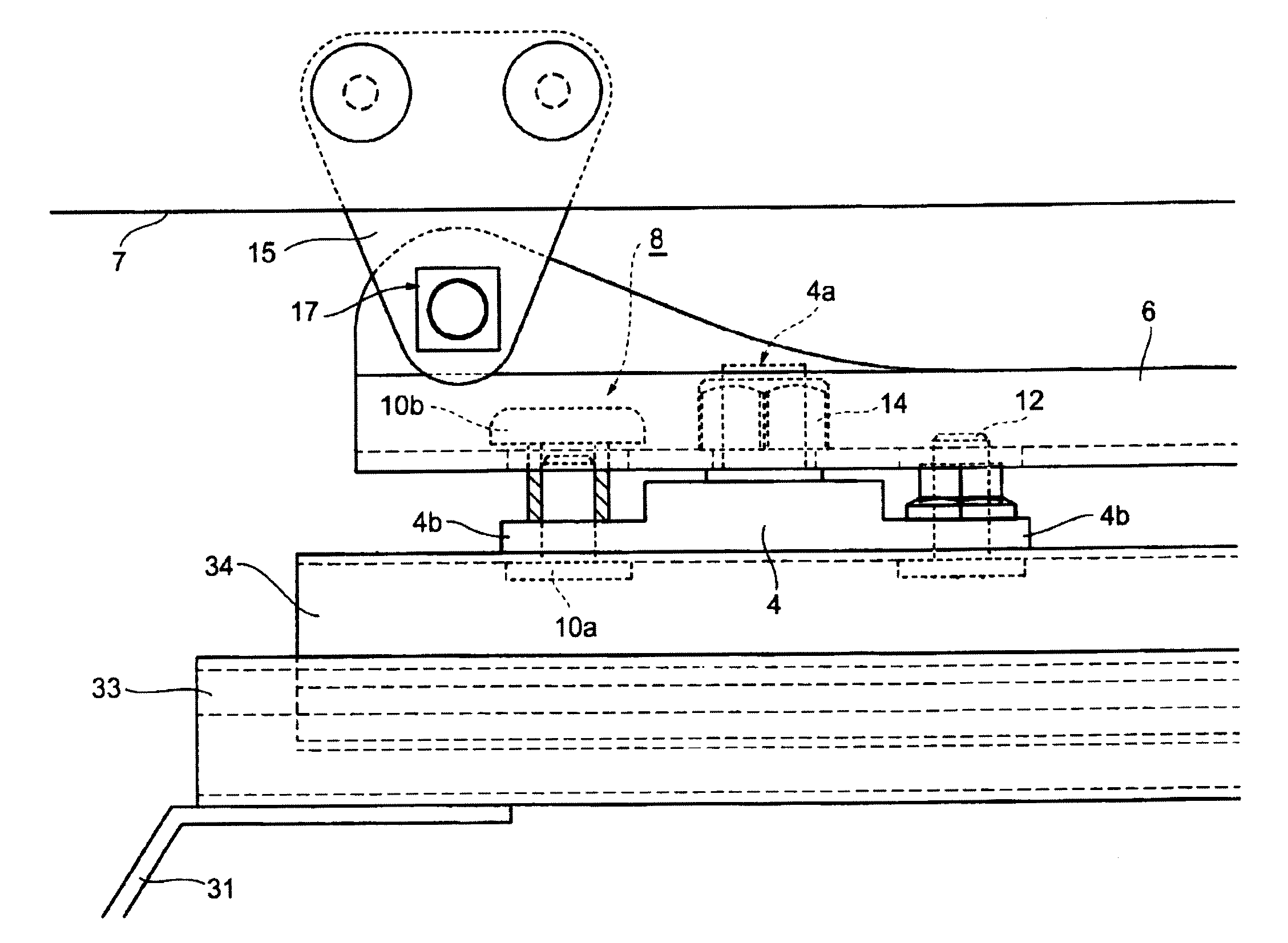
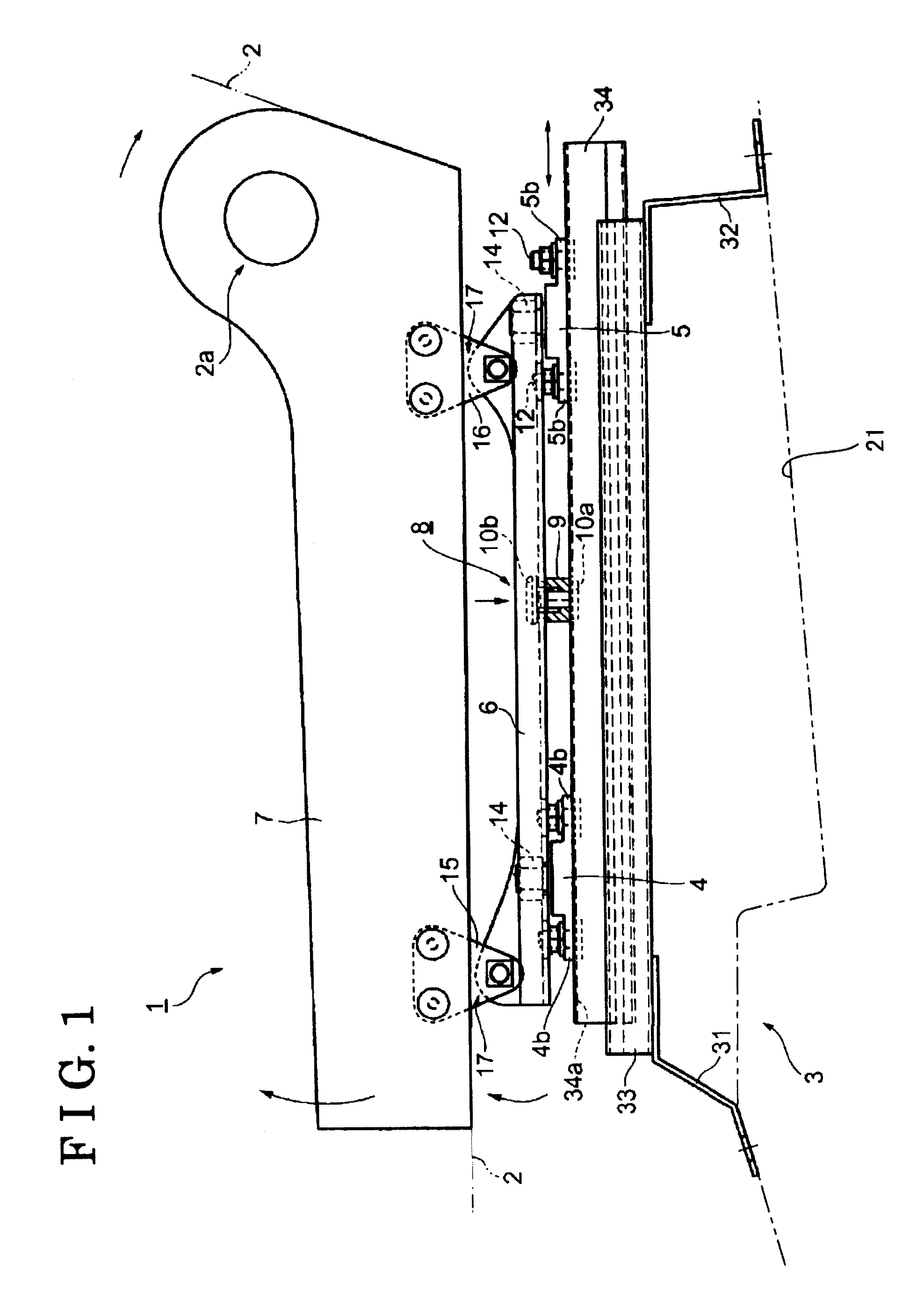
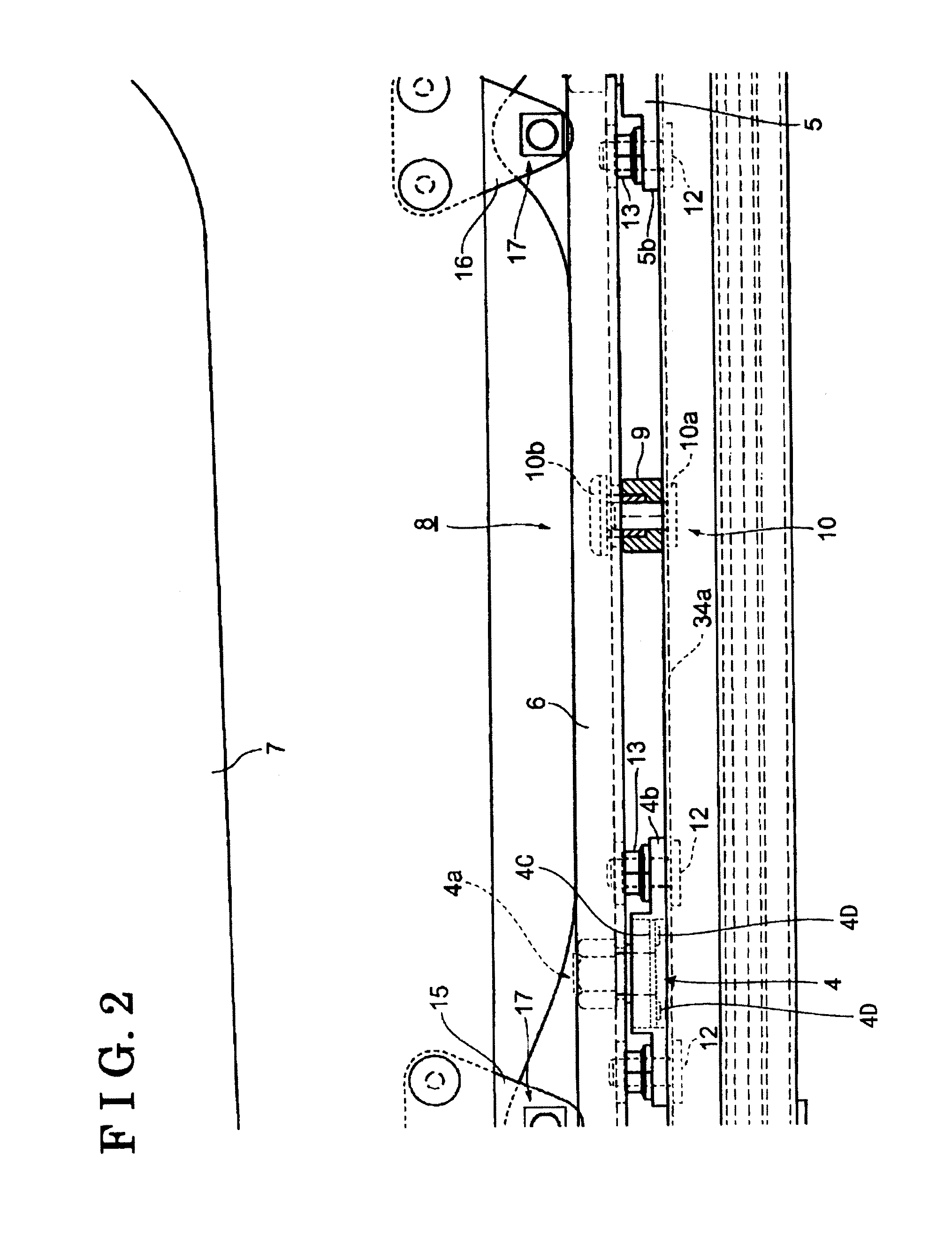
[0031] The stopper 8 in the first embodiment is disposed in the vicinity of an intermediate position (a center) between the load sensor 4 and the load sensor 5 (refer to FIGS. 1 and 2), which are arranged along the forward and backward direction. An intermediate portion of the connecting member 6 is significantly deformed when the load is applied. Thus, the stopper 8 prevents the deformation of the connecting member 6 by physically controlling movement of the intermediate portion of the connecting member 6. Specifically, the stopper 8 is composed of a protruding control member 9 and a control member 10. The protruding control member 9 is interposed between the connecting member 6 and the upper rail 34 and controls the deformation of the connecting member 6 toward the supporting base 3. The control member 10 sandwiches the connecting member 6 and the upper rail 34 so as to control the deformation of the connecting member 6 in the direction opposite to the upper rail 34 (refer to FIGS...

second embodiment

[0035] The stopper 8 in the embodiment is composed of a protruding control member 9 formed in the connecting member 6 so as to be in contact with a part of the front load sensor 4 such as the flange portion 4b (refer to FIGS. 3 and 4). In the embodiment, the protruding control members 9 are provided at the front and at the rear of the load sensor 4 to control the movement of the connecting member 6 in both directions, the deformation of the connecting member 6 toward the supporting base 3 and the deformation of the connecting member 6 in the direction opposite to the supporting base 3. The protruding control member 9 may be formed by welding a member to the connecting member 6 or may be formed by cutting away a part of the connecting member 6. Any form of the protruding control member 9 can be acceptable as far as the movement of the connecting member 6 is controlled when the excessive load is applied. Also, it is preferable to dispose the protruding control member 9 at the front an...

third embodiment

[0036] The stopper 8 in the third embodiment is configured by providing a control member 10, which is composed of a bolt 10a and a nut 10b, so as to sandwich the flange portion 4b of the front load sensor 4 (and the upper rail 34) and the connecting member 6 (refer to FIGS. 5 and 6). The above-described control member 10 controls the deformation of the connecting member 6 in the direction opposite to the supporting base 3 at a position, i.e., the front side of the load sensor 4. In the embodiment, the bolt 10a is disposed at a lower side. However, it is possible to reverse the positions of the bolt 10a and the nut 10b. Similarly to the above-described case, a clearance between the nut 10b and the bottom surface of the connecting member 6 is formed to have a width so that the movement of the connecting member 6 is not blocked by the control member 10 when the normal load is applied, and the movement of the connecting member 6 is controlled when the excessive load due to the impact or...


PUM


Abstract

A load detecting device for a vehicle seat includes a supporting base adapted to be mounted on a floor of the vehicle, a plurality of load sensors arranged along a forward and backward direction of a seat for the vehicle on the supporting base, the load sensors including a load input portion, a deflection portion deflecting by a load and a deflection gauge measuring an amount of deflection, the load sensors detecting the load based on the amount of deflection measured by the deflection gauge, a connecting member connecting the load input portions, a seat supporting member connected to the connecting member and adapted to support the seat for the vehicle, the seat supporting member transmitting load to the connecting member, and a stopper preventing deformation of the connecting member in a vertical direction of the seat when load which exceeding a predetermined value is applied to the connecting member.

Description

CROSS REFERENCE TO RELATED APPLICATIONS [0001] This application is based on and claims priority under 35 U.S.C § 119 with respect to Japanese Patent Application 2006-174222, filed on Jun. 23, 2006, the entire content of which is incorporated herein by reference. FIELD OF THE INVENTION [0002] This invention relates to a load detecting device for a vehicle seat. More specifically, the invention relates to improvement of a structure in a load detecting device for a vehicle seat for measuring load applied to a seat for a vehicle. BACKGROUND [0003] For example, a mechanism is provided for moving a seating surface for a vehicle up and down via a link. In association with the mechanism, a load detecting device for a vehicle seat, which measures load applied to the seat for the vehicle, is used as follows. The device is used for controlling an airbag. For example, the airbag is switched on and off according to the detected load value. Many of the load detecting devices for the vehicle seat ...

Claims


Application Information

Patent Timeline
IPC IPC(8): A47C31/12B60N2/90
CPCB60N2/002
Inventor KAWABATA, HIDEKIINAYOSHI, MUNETOICHIHARA, KANFUJII, HIROYUKIAKIZUKI, KENICHIROIZAWA, MINORU
Owner AISIN SEIKI KK
Why Eureka
Try Eureka