Winding arrangement for a linear motor with coil pairs arranged in parallel made from a continuous electrical conductor

Pending Publication Date: 2022-01-27
INTRASYS - INNOVATIVE TRANSPORT SYST
View PDF0 Cites 0 Cited by
  • Summary
  • Abstract
  • Description
  • Claims
  • Application Information

AI Technical Summary

Benefits of technology

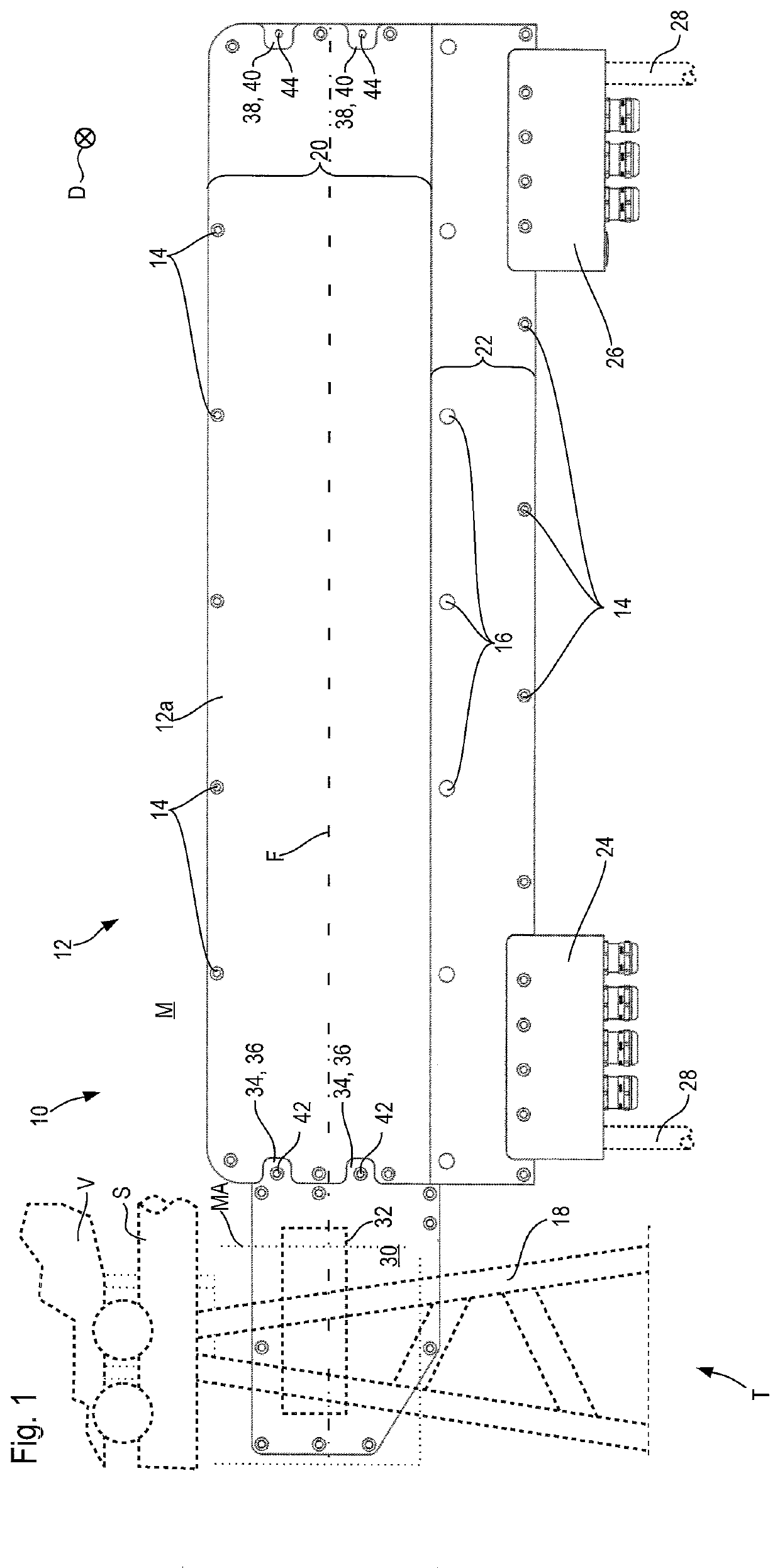
[0047]Likewise, a region of the coil housing free from electrical conductors of the coils and the connecting conductor sections connecting them can be configured to accommodate at least one sensor. For example, at least one sensor recess can be configured in the coil housing to accommodate a sensor, such as for instance a temperature sensor. Preferably the sensor recess is also located in the connection area. A signal transmission line, which links the sensor with a control device, can be laid in a separate signal conductor cavity in the coil housing, in particular in its connection area. The signal conductor cavity can be section-wise identical with an aforementioned conductor cavity for accommodating the connecting conductor sections, such that section-wise the signal transmission line of a sensor and a connecting conductor section are laid in one and the same cavity in the coil housing. Section-wise, in particular in the connection region of the coil housing, the signal conductor cavity can be provided outside the first and the second layer of the coils, in order to prevent clashes with the connecting conductor sections.
[0048]Knowing the position of the magnet arrangement or inductive arrangement respectively moving relative to the winding arrangeme

Problems solved by technology

Since usually in the manufacturing of a winding arrangement first the coils are arranged and after their arrangement are electrically connected to each other, i.e. wired up, the complicated arrangement and wiring of the coils of the winding arrangement known from DE 10 2006 023 493 B4 harbors an undesirably high risk of incorrect wiring of the individual coils with e

Method used


Image

  • Winding arrangement for a linear motor with coil pairs arranged in parallel made from a continuous electrical conductor
  • Winding arrangement for a linear motor with coil pairs arranged in parallel made from a continuous electrical conductor
  • Winding arrangement for a linear motor with coil pairs arranged in parallel made from a continuous electrical conductor

Examples


Example

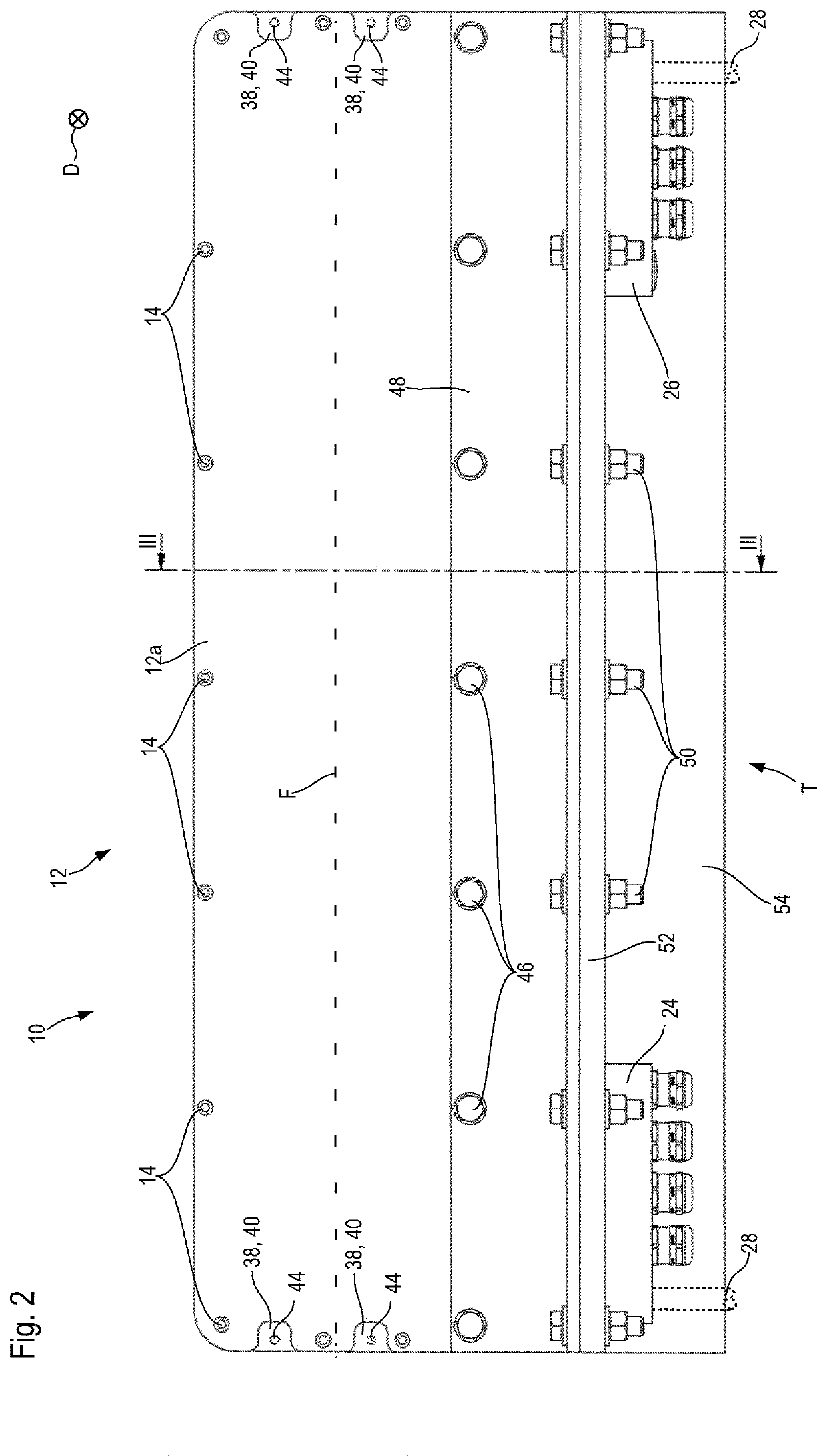
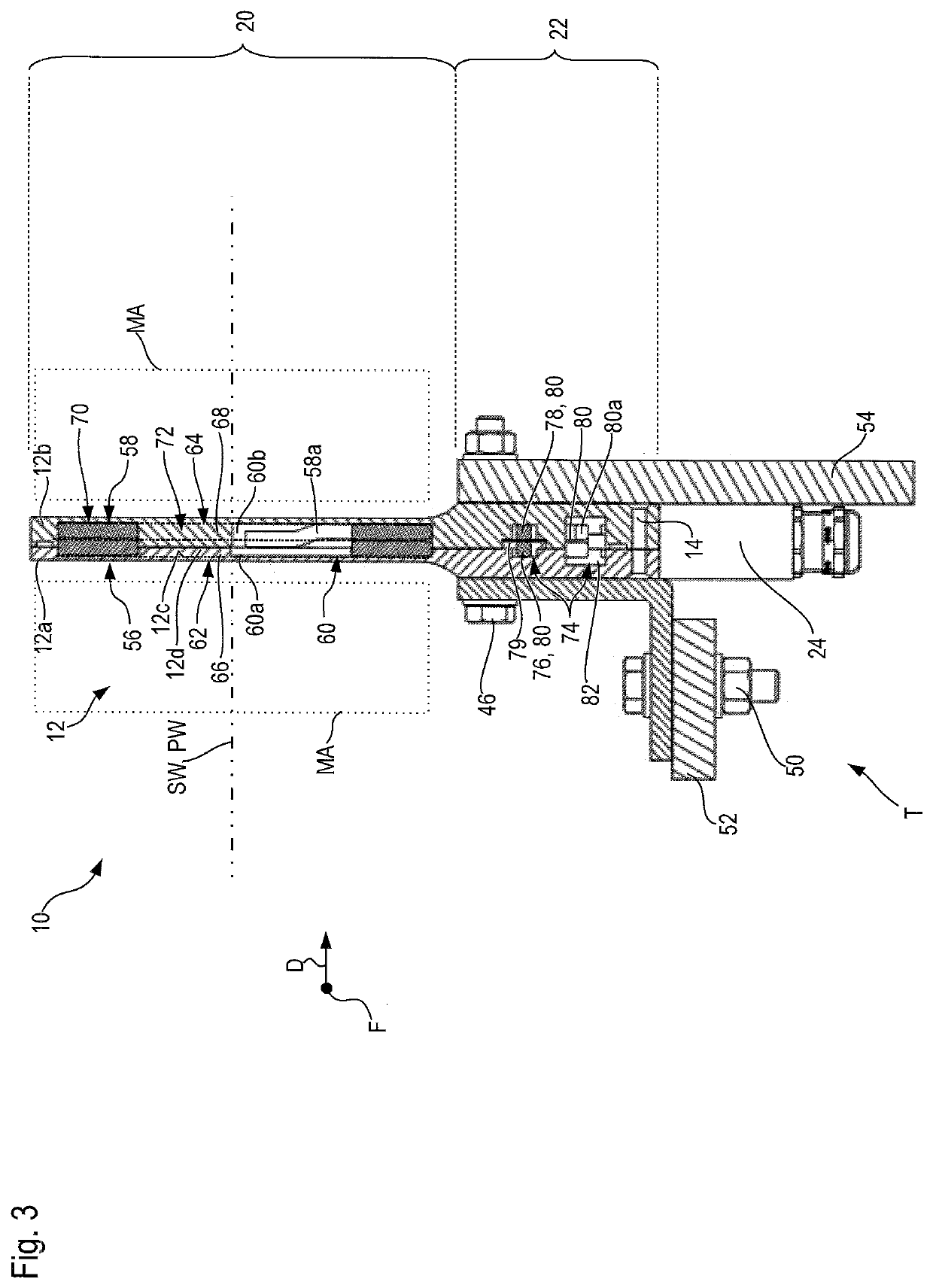
[0105]FIG. 5 depicts a second embodiment of a winding arrangement 111 and / or of a stator 110 respectively of the present invention. Identical and functionally identical components and component sections as in the first embodiment of FIGS. 1 to 4 are provided in the second embodiment of FIG. 5 with the same reference labels, but increased numerically by 100. The second embodiment of FIG. 5 will hereunder be described only in so far as it differs from the first embodiment of FIGS. 1 to 4, to the description of which reference will be made otherwise also to elucidate the second embodiment of FIG. 5.

Example

[0106]The essential difference between the first embodiment and the second embodiment of FIG. 5 consists in the design of the cooling duct 188. In contrast to the first embodiment, in the second embodiment of FIG. 5 the cooling medium's flow in the interior of the coil housing 12 follows completely the course of the electrical conductors 173, 176, and 178. Thus, the conductor cavities 186 are configured as flow ducts 190, or put another way: the connecting conductor arrangements 180 are arranged in flow ducts 190.

[0107]Thereby there is assigned to each electrical phase one cooling duct 188, of which the flow ducts 190 respectively are a part. Furthermore, the accommodating cavities 160 and moreover the changeover region 182 form a further part of each cooling duct 188, which however in the second embodiment is subdivided by means of discontinuities 183 into a plurality of compartments. Cooling medium can flow in each cooling duct 188 without impacting the cooling medium flow in a co...

Example

[0110]FIG. 6 depicts a third embodiment of a winding arrangement 211 and a stator 210 respectively of the present invention. Identical and functionally identical components and component sections as in the first embodiment of FIGS. 1 to 4 are provided in the third embodiment of FIG. 6 with the same reference labels, but increased numerically by 200. The third embodiment of FIG. 6 will hereunder be described only in so far as it differs from the first embodiment of FIGS. 1 to 4, to the description of which reference will be made otherwise also to elucidate the third embodiment of FIG. 6.

[0111]The third embodiment of the stator 210 and of the winding arrangement 211 respectively corresponds essentially to the first embodiment, where however in the third embodiment no cooling duct is provided. It can, however, be provided, namely either as a serial cooling duct as in the first embodiment, according to which flow ducts 90 connect with each other accommodating cavities 60 immediately adj...


PUM


Abstract

A conductive winding arrangement for generating a varying magnetic field in the neighborhood of the winding arrangement, comprising a plurality of coil pairs arranged one after another along a sequence axis with a virtual coil pair winding axis oriented transversely to the sequence axis, of which each coil pair exhibits a first coil and a second coil, each with a coil winding axis parallel or collinear respectively to the coil pair winding axis, where the first and the second coil are arranged axially adjacent to each other relative to the coil pair winding axis in such a way that turns of the first and of the second coil are axially adjacent to each other and that eye regions of the first coil and of the second coil are axially adjacent to each other while forming a common coil-pair eye region, where the coil pair winding axis penetrates through the coil-pair eye region; at least one coil pair being configured as a single conductor coil pair, in which the first and the second coil each exhibit a connecting section located radially outside relative to the coil pair winding axis for connecting to a phase of a power supply or to a further coil and in the coil-pair eye region they are connected to each other electroconductively.

Description

[0001]This Application claims priority in German Patent Application DE 10 2020 119 589.3 filed on Jul. 24, 2020, which is incorporated by reference herein.[0002]The present invention concerns a conductive winding arrangement for generating a temporally and spatially varying magnetic field in the spatial neighborhood of the winding arrangement, comprising a plurality of coils, of which each exhibits a wire wound in several turns around a virtual coil winding axis, where the coil winding axis penetrates through a radially inner region of the coil free from wire turns, where the winding arrangement exhibits a first layer of first coils arranged one after another without overlapping along a sequence axis with coil winding axes parallel to each other and exhibits a second layer of second coils arranged one after another without overlapping along the sequence axis with winding axes parallel to each other, where the winding arrangement comprises a plurality of coil pairs arranged one after...

Claims


Application Information

Patent Timeline
IPC IPC(8): H01F27/28G01D5/20
CPCH01F27/2823G01D5/204H01F27/2876H02K1/32H02K9/19H02K3/28H02K41/02H02K3/47H02K3/24H02K5/20
Inventor GRIMM, ARNULFHOLLMER, TOBIAS
Owner INTRASYS - INNOVATIVE TRANSPORT SYST
Why Eureka
Try Eureka