
Method of Intelligent Power Distribution for System with Double Charging Terminals

a charging terminal and intelligent technology, applied in the direction of charging stations, electric vehicle charging technology, transportation and packaging, etc., can solve the problems of inconvenient electric vehicle driver, waste of charging resources in some portions, and inability to guarantee the consistency of charging positions, etc., to achieve the maximum efficiency of power use of the charging system

Active Publication Date: 2018-02-22
ZEROVA TECH TAIWAN LTD
View PDF11 Cites 7 Cited by
  • Summary
  • Abstract
  • Description
  • Claims
  • Application Information

AI Technical Summary

Benefits of technology

The patent is about a method for efficiently distributing power in a charging system with double charging terminals. This method helps to maximize the use of power, which is important for ensuring that the charging system operates at its best. Overall, the invention optimizes power distribution to improve the performance of the charging system.

Problems solved by technology

However, because of the limitation of charging station, demand of charging position of electric vehicle for charging station is more diverse, it can't guarantee the consistency of charging position.
If the vehicle uses a single charging interface mode, it will lead to a waste of charging resources in some portions.
In addition, the current charging equipment can only one-to-one charge to an electric vehicle, charging for a long time, so that the electric vehicle loads a larger capacity of battery to ensure that it can run enough mileage.
It is not convenient for driver of the electric vehicle due to a waste of time.
However, for the communication of sending information during idle time of CP signal, it needs to wait for the idle time, and therefore it has some disadvantages such as, lower time utilization rate, poor instantaneity of data, easily interfering by power line as charging, without recognizing data, lower transmission success rate, and the reliability should be improved.
For data transmission by carrier wave, charging time for high power electric vehicle charged by a single charging gun is too long, so it unfavorable for the actual operation.

Method used

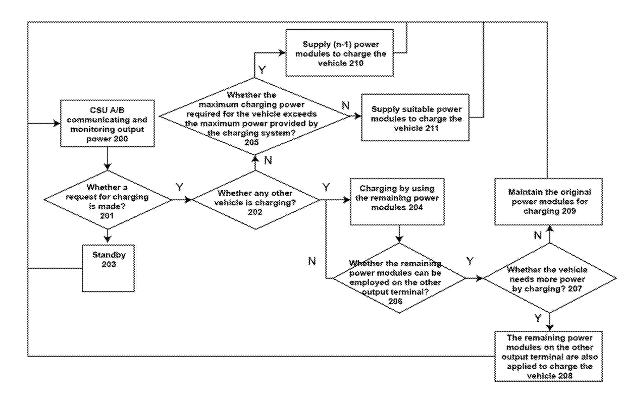
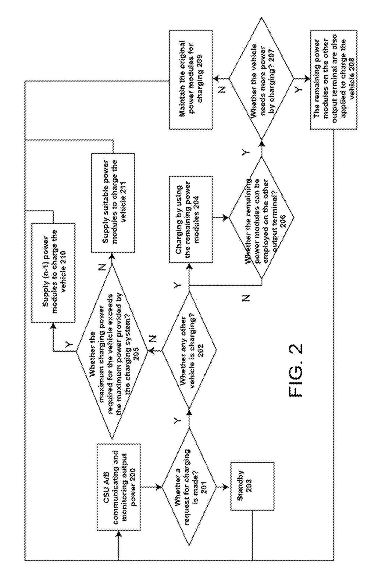

Image

  • Method of Intelligent Power Distribution for System with Double Charging Terminals
  • Method of Intelligent Power Distribution for System with Double Charging Terminals
  • Method of Intelligent Power Distribution for System with Double Charging Terminals

Examples


Embodiment Construction

[0022]Some preferred embodiments of the present invention will now be described in greater detail. However, it should be recognized that the preferred embodiments of the present invention are provided for illustration rather than limiting the present invention. In addition, the present invention can be practiced in a wide range of other embodiments besides those explicitly described, and the scope of the present invention is not expressly limited except as specified in the accompanying claims.

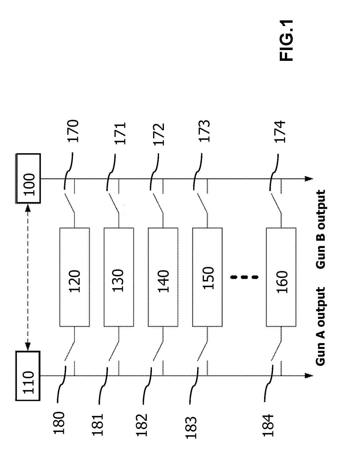
[0023]The present invention provides a method of energy distribution in a charging system with double charging terminals (gun A, gun B) for charging efficiently to achieve optimum power (energy) distribution of charging. Two central supervised units (CSU) are employed to monitor the state of output power of the charging system. When only a single gun (Gun A) is requested for charging, the internal output relays are regulated and controlled in accordance with charging current demand of the vehic...


PUM


Abstract

A method of intelligent power distribution for a charging system with double charging terminals is provided. The method of the present invention comprises the following steps, determining whether a first vehicle is requesting for charging or not. Then, the next step is determining whether a second vehicle is charging in the system or not. If the determination is affirmative, the first vehicle is then charged by remainder power modules. In the following, it is determining whether remainder power modules can be used for a second output terminal. Subsequently, it is determining whether the first vehicle needs more power by charging. If the determination is affirmative, the remainder power modules are charging to the first vehicle via the second output terminal.

Description

CROSS-REFERENCE TO RELATED APPLICATIONS[0001]This application is a Counter Part Application of TAIWAN Patent Application Ser. No. 105126143, filed on Aug. 16, 2016. The content of the above-mentioned patent applications is hereby incorporated by reference herein in its entirety and made a part of this specification.TECHNICAL FIELD[0002]The present invention generally relates to a charging system of a vehicle, in particular, to a method of intelligent power distribution for system with double charging terminals.DESCRIPTION OF RELATED ARTS[0003]Traditionally, fuel vehicle mainly depends on petroleum, while shortage of oil and gas exhaust of fuel vehicle caused serious environment pollution, it would increasingly urgent for human being to further develop new green transportation. As a green transportation, electric vehicles not only save energy and improve comprehensive utilization of energy significantly, and environmental benefits are obvious, as compared with conventional vehicle, f...

Claims


Application Information

Patent Timeline
Patent Type & Authority Applications(United States)
IPC IPC(8): B60L11/18
CPCB60L11/1838B60L53/63B60L53/64B60L53/00B60L53/305B60L53/62B60L53/11Y02E60/00Y02T10/70Y02T10/7072Y02T90/12Y02T90/14Y02T90/16Y04S10/126
Inventor CHEN, CHUN-CHENLEE, JIAN-HSIENGYEH, YING-CHIEHKU, HSIAO-TUNG
Owner ZEROVA TECH TAIWAN LTD
Learn More