Improvements in 3D printing

a 3d printing and improvement technology, applied in the field of 3d printing, can solve the problems of molten plastic to solidify often the rate limit step, the speed of creating objects remains an issue, and the time required, so as to improve the resolution of printed articles, reduce the penetration depth, and improve the effect of resolution

Inactive Publication Date: 2018-03-01
GIZMO 3D PRINTERS
View PDF6 Cites 6 Cited by
  • Summary
  • Abstract
  • Description
  • Claims
  • Application Information

AI Technical Summary

Benefits of technology

[0042]Without being bound by theory, it is thought that the light projected from the image source penetrates into the resin bath. The intensity of the light decreases as it penetrates further into the bath. Because of this, polymerisation typically occurs close to the top surface of the liquid resin where the light intensity is high enough to initiate polymerisation. The depth that the light is intense enough to initiate polymerisation is typically the depth polymerised for each image projected onto the surface of the resin, and can be called the penetration depth. The amount of material added to the printed article is dependent on the penetration depth. For example, a penetration depth of 35 μm would mean each image will add a layer 35 μm thick of material to the article. This penetration depth can be increased or decreased depending on the intensity of the lamps used to project the image, the type of resin used and / or the wavelength of the light emitted from the image source. Additives may also be added to the resin to absorb a portion of the light to control the depth the light penetrates into the resin. For example, pigments can be added to the resin to selectively absorb light and decrease the penetration depth. This may help to improve the resolution of the printed article.
[0043]The image as generated may have areas of high brightness or greater light intensity relative to other areas of the image. The areas of greater light intensity are most frequently at the centre of the image as projected; and areas of relatively less light intensity are typically at the peripheral edges of the image as projected. The area of greater light intensity at the centre of a projected image can be referred to as a hotspot. When there are images overlapping from multiple image sources, the hotspot at the centre of the image can be of greater intensity. It is desirable for the resin to cure at an even rate across the single 2D plane. A hotspot when projected onto a resin bath can cause accelerated resin curing in that spot while resin in other areas takes longer to cure. In order to compensate for the hotspots, there can be a hotspot compensation process undertaken before the printing process. The hotspot compensation process can allow the user to create any number of pixels having an intensity that can be changed by computer prior to the image being projected. This software instruction effectively becomes a mask over a normal image / layer so that the power of the middle of the image / layer can be reduced to the same intensity of the outer pixels. The hotspot compensation may additionally be used during overlap of adjacent images at a border.

Problems solved by technology

Therefore, the speed of creating objects still remains an issue in using 3D printing for widespread manufacturing processes.
However, the time required to melt, deposit and then allow the molten plastic to solidify is often the rate limiting step in the time required to deposit each layer.
Further, inadequate deposition can lead to structural flaws in the object that can affect its mechanical properties.
This can be improved, but it is often at a sacrifice for the time required to deposit each layer.
3D printers that use methods to polymerise resins often have better resolution than their extruded plastic counterparts, but they are more expensive.
The operation processes involved in creating an object using resins is also more complex due to the use of specialty lights, lasers or tracking systems.

Method used


Image

  • Improvements in 3D printing
  • Improvements in 3D printing
  • Improvements in 3D printing

Examples


Embodiment Construction

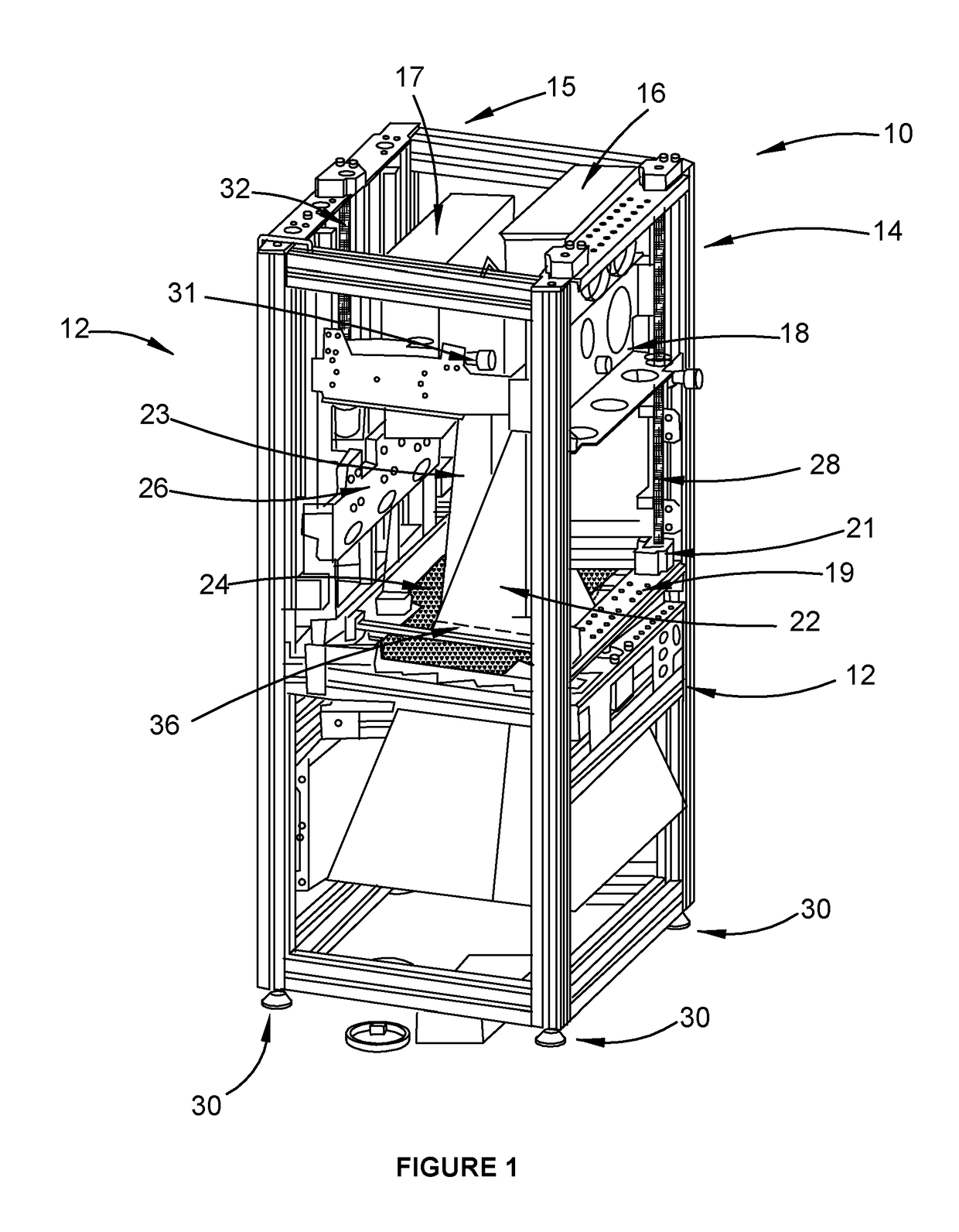
[0074]A 3D printer 10 is shown in FIG. 1. The printer 10 is made from a frame 12 that has vertical supports 14 and horizontal supports 15 to define a hollow supporting structure. The length of the vertical supports 14 are longer than the length of the horizontal supports 15. However, as should be appreciated, the length of the vertical and horizontal supports may be of any length, and the length may be determined by the size of the article being printed. The vertical supports 14 and horizontal supports 15 can be made from any material suitable to construct such a frame. In an embodiment, the supports are made from aluminum. In an embodiment, the supports are made from a plastic and / or fibre reinforced plastic. Located at the base of the frame 12 are feet 30. The feet 30 are individually adjustable to allow the article plate 24 to be substantially level. However, other levelling means known in the art can also be used to level the printer 10, for example, hydraulic or air cushions an...


PUM

PropertyMeasurementUnit
temperatureaaaaaaaaaa

Abstract

A method of 3D printing an article is described, the method comprising the steps of projecting images onto a liquid resin from a plurality of cooperating image sources; aligning the images from the first and second sources at least in a single 2D plane in the liquid resin; moving a plate relative to the 2D plane, wherein the moving is substantially continuous; and allowing the liquid resin to cure upon expose to the image in the 2D plane, thereby forming the printed article. The curing of the resin under the influence of the light emitted from the plurality of image sources can allow for a fast printing process.

Description

TECHNICAL FIELD[0001]The present invention relates to 3D printing.BACKGROUND[0002]3D printing is an additive manufacturing method that can be used to create a wide variety of objects. In some instances, 3D printing can produce objects that cannot otherwise be created using traditional manufacturing processes. To create an object using a 3D printer, a layer of material is deposited across a 2D plane, and then another layer of material is deposited on top of the previous layer. This process is repeated multiple times until the final object is obtained. This type of manufacture can also be known as layer-by-layer manufacture, bottom-up-manufacture, or additive manufacture.[0003]Because 3D printers use a layer-by-layer approach to create an object, the time required to create the object is primarily determined by the time taken to deposit each layer. The time increases significantly as the size of the object increases. Therefore, the speed of creating objects still remains an issue in u...

Claims


Application Information

Patent Timeline
Patent Type & Authority Applications(United States)
IPC IPC(8): B29C64/129B29C35/08B29C64/236
CPCB29C64/129B29C35/0805B29C64/236B29C2035/0827B33Y10/00B33Y30/00B29C2035/0811B29C64/277B29C64/295
Inventor DU TOIT, KOBUS
Owner GIZMO 3D PRINTERS
Why Eureka
Try Eureka