Method for controlled operation of a heated, in particular regeneratively heated, industrial furnace, open-loop and closed-loop control unit, and heatable industrial furnace

a technology of industrial furnaces and control units, which is applied in the direction of furnaces, lighting and heating apparatus, manufacturing tools, etc., can solve the problems of undesired inaccuracy of control, inability to adjust the temperature,

Active Publication Date: 2018-03-01
STG COMBUSTION CONTROL
View PDF3 Cites 1 Cited by
  • Summary
  • Abstract
  • Description
  • Claims
  • Application Information

AI Technical Summary

Benefits of technology

[0021]Accordingly, a control method that compensates for the influence of variations of the actual infiltrated air and the influence of variations of the fuel gas composition in different con

Problems solved by technology

On account of the high heat-retaining capacity of an industrial furnace, including the material it is heating, however, changes in temperature usually only become apparent after hours, and their correction takes a similarly great or longer amount of time, because the adapted quantity of fuel gas first has to be found by the control algorithm.
However, experience shows that, in particular for near-stoichiometric combustion, the introduction of a controlling correction, first of the quantity of fuel gas and then once again of the quantity of combustion air, leads to an undesired inaccuracy of the control, which for the method thus described is evidently corrected again subsequently by the additional feedforwarding of a measured O2 concentration in the flue gas.
For the increasingly more important case of near-stoichiometric or deliberately substoichiometric combustion, this method is no longer suitable.
However, the conventional control methods thus prove to be too slow.
In particular, they do

Method used


Image

  • Method for controlled operation of a heated, in particular regeneratively heated, industrial furnace, open-loop and closed-loop control unit, and heatable industrial furnace
  • Method for controlled operation of a heated, in particular regeneratively heated, industrial furnace, open-loop and closed-loop control unit, and heatable industrial furnace
  • Method for controlled operation of a heated, in particular regeneratively heated, industrial furnace, open-loop and closed-loop control unit, and heatable industrial furnace

Examples


Embodiment Construction

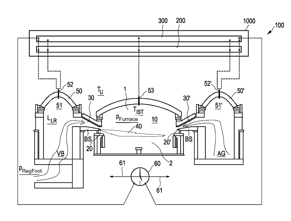
[0131]FIG. 1 shows in a simplified representation a regeneratively heated industrial furnace 100 with a furnace chamber 10, the upper furnace chamber 1 of which is controlled as a controlled system and in which the lower furnace chamber 2 has a glass melting end that is not shown any more specifically. Glass contained in the glass melting end is heated by way of the furnace chamber 10 above the melting temperature and is melted and suitably treated for the production of flat glass or the like. The industrial furnace 100 is in the present case heated by fuel, in the present case in the form of fuel gas, being injected into the upper furnace 1 by way of a number of laterally attached fuel injectors 20. Of the fuel injectors 20, in the present case a left injector 20 is shown. Of the further fuel injectors 20′, in the present case a right injector 20′ is shown. For the sake of simplicity, the same designations are used below for parts that are the same or similar or parts that have the...


PUM

PropertyMeasurementUnit
Temperatureaaaaaaaaaa
Fractionaaaaaaaaaa
Timeaaaaaaaaaa

Abstract

A method for controlled operation of a heated industrial furnace having a furnace chamber is provided. Fuel is conducted into the furnace chamber virtually without combustion air and a gaseous oxygen carrier is also conducted. The supply of fuel and the gaseous oxygen carrier is controlled by a control loop. A first adjustable manipulated variable in the form of a flow of fuel and/or a second adjustable manipulated variable in the form of a flow of the gaseous oxygen carrier is set by a final controlling element. In the control loop, an energy requirement is determined and fed to a quantitative control and to a quantitative fuel control for the fuel. The flow of the gaseous oxygen carrier is determined as a process value of a flow of the gaseous oxygen carrier and the flow of fuel is determined as a process value of a volumetric flow of fuel.

Description

BACKGROUNDTechnical Field[0001]The invention relates to a method for the controlled operation of a heated industrial furnace, in particular a regeneratively heated industrial furnace, and to an open-loop and closed-loop control unit and to a heatable industrial furnace.Description of the Related Art[0002]In principle, an industrial furnace of the type mentioned at the beginning is not restricted to use in glass production. For example, an industrial furnace of the type mentioned at the beginning can also be used in metal production or the like. A regenerative industrial furnace of the type mentioned at the beginning has however proven to be particularly suitable in glass production for the melting of glass.[0003]In the case of a heated industrial furnace, in particular a regeneratively heated industrial furnace, there is often a separate supply of fuel and of a gaseous oxygen carrier, in particular combustion air and / or oxygen, so that for this reason alone a special open-loop and c...

Claims


Application Information

Patent Timeline
IPC IPC(8): C03B5/24C03B5/237C03B5/235F23N1/02F27B9/30F23N5/20
CPCC03B5/24C03B5/237C03B5/2353F23N1/022F27B9/3044F23N5/203F23N2023/36F23N2025/08F23N5/022F23N2223/36F23N2225/08F23N2237/28C03B5/235Y02P40/50F23N2237/08
Inventor HEMMANN, PETERBIRLE, ANDREASHEMMANN, NORWIDKORTT, JURGEN
Owner STG COMBUSTION CONTROL
Why Eureka
Try Eureka