Acoustic diaphragm, and method of fabricating acoustic diaphragm

a technology of acoustic diaphragm and acoustic diaphragm, which is applied in the direction of transducer diaphragm, transducer details, instruments, etc., can solve the problems of large energy consumption for fabrication, heavy pollution of dies, and difficult to deal with environmental measures on the edge composed of vulcanized rubber, etc., to achieve excellent workability, excellent workability, and excellent workability.

Inactive Publication Date: 2011-07-19
SONY CORP
View PDF8 Cites 3 Cited by
  • Summary
  • Abstract
  • Description
  • Claims
  • Application Information

AI Technical Summary

Benefits of technology

[0008]Another disadvantage relates to a vulcanization time of as long as 10 minutes or more in the molding process, resulting in heavier pollution of dies and larger energy consumption for the fabrication. In the phase of mass production, an increase in the number of surfaces of the dies is inevitable when productivity is sought after, resulting in variation in accuracy of thin and fine mold products.
[0014]The present invention provides an acoustic diaphragm having a loudspeaker edge minimizing differences in the elastic modulus and in stretchability depending on the direction of molding, making use of an excellent function of a thermoplastic elastomer, and a method of fabricating the acoustic diaphragm.
[0016]By composing the edge using an polyolefinic elastomer containing a soft segment having rubber particles of a small diameter uniformly dispersed therein, which has an excellent workability even with a small content of an olefinic resin serving as a hard segment, it is made possible to proceed molding while keeping a material composition capable of reducing a ratio of resin component in the hard segment portion which tends to concentrate to a surficial portion of mold products in the process of molding and solidification of the mold products, and of ensuring a necessary level of fluidity of the elastomer.
[0017]A method of fabricating an acoustic diaphragm according to an embodiment of the present invention includes a step of filling an injector with a polyolefinic elastomer, as a material to be injected for forming an edge composed of a thermoplastic elastomer, containing a soft segment having rubber particles of a constant small diameter uniformly dispersed therein, which has an excellent workability even with a small content of an olefinic resin serving as a hard segment; a step of injecting the material through a gate in a die being opened at a position corresponding to a portion in a circumference of the edge; and a step of carrying out injection molding to thereby mold the edge into a shape allowing the resin to be aligned as being not causative of anisotropy in the physical characteristics of the edge, as a result of thin-wall molding by the injection molding.
[0018]By filling an injector with a polyolefinic elastomer, as a material to be injected for forming the edge composed of the thermoplastic elastomer, which contains a soft segment having rubber particles of a constant small diameter uniformly dispersed therein, which has an excellent workability even with a small content of an olefinic resin serving as a hard segment, and by injecting the material through a gate in a die being opened at a position corresponding to a portion in a circumference of the edge, the edge can be molded into a shape allowing the resin to be aligned as being not causative of anisotropy in the physical characteristics of the edge, as a result of thin-wall molding by the injection molding, and thereby it is made possible to reduce the ratio of resin component in the hard segment portion which tends to concentrate to the surficial portion of the mold products in the process of molding and solidification of the mold products, and to ensure a necessary level of fluidity of the elastomer.

Problems solved by technology

However with recent increase in public attention to environmental measures, the edge composed of the vulcanized rubber has appeared to be difficult to deal with the environmental measures, because such edge cannot allow removal of residual sulfur content, and material recycling.
Another disadvantage relates to a vulcanization time of as long as 10 minutes or more in the molding process, resulting in heavier pollution of dies and larger energy consumption for the fabrication.
On the other hand, the techniques using the thermoplastic elastomers for composing the edge as described in Japanese Patent Application Publication Nos. 2003-78998 and H7-138882 in the above are, however, only limitedly applied in practice, because of the poorer sound quality resulting from their poorer damping property and flexibility, as compared with those of the vulcanized rubber.

Method used


Image

  • Acoustic diaphragm, and method of fabricating acoustic diaphragm
  • Acoustic diaphragm, and method of fabricating acoustic diaphragm
  • Acoustic diaphragm, and method of fabricating acoustic diaphragm

Examples


Embodiment Construction

[0022]Paragraphs below will detail embodiments of the present invention, referring to the attached drawings.

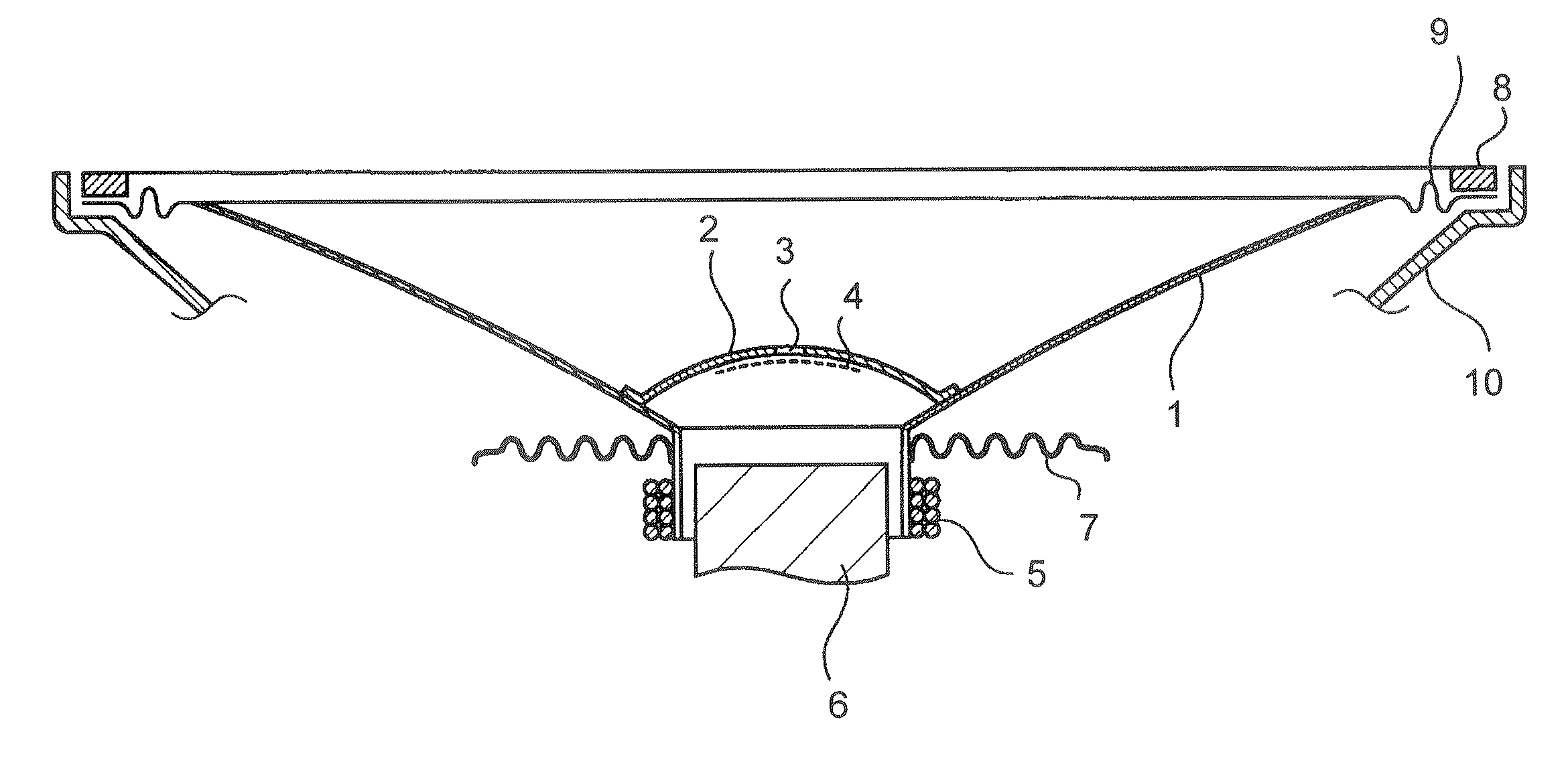
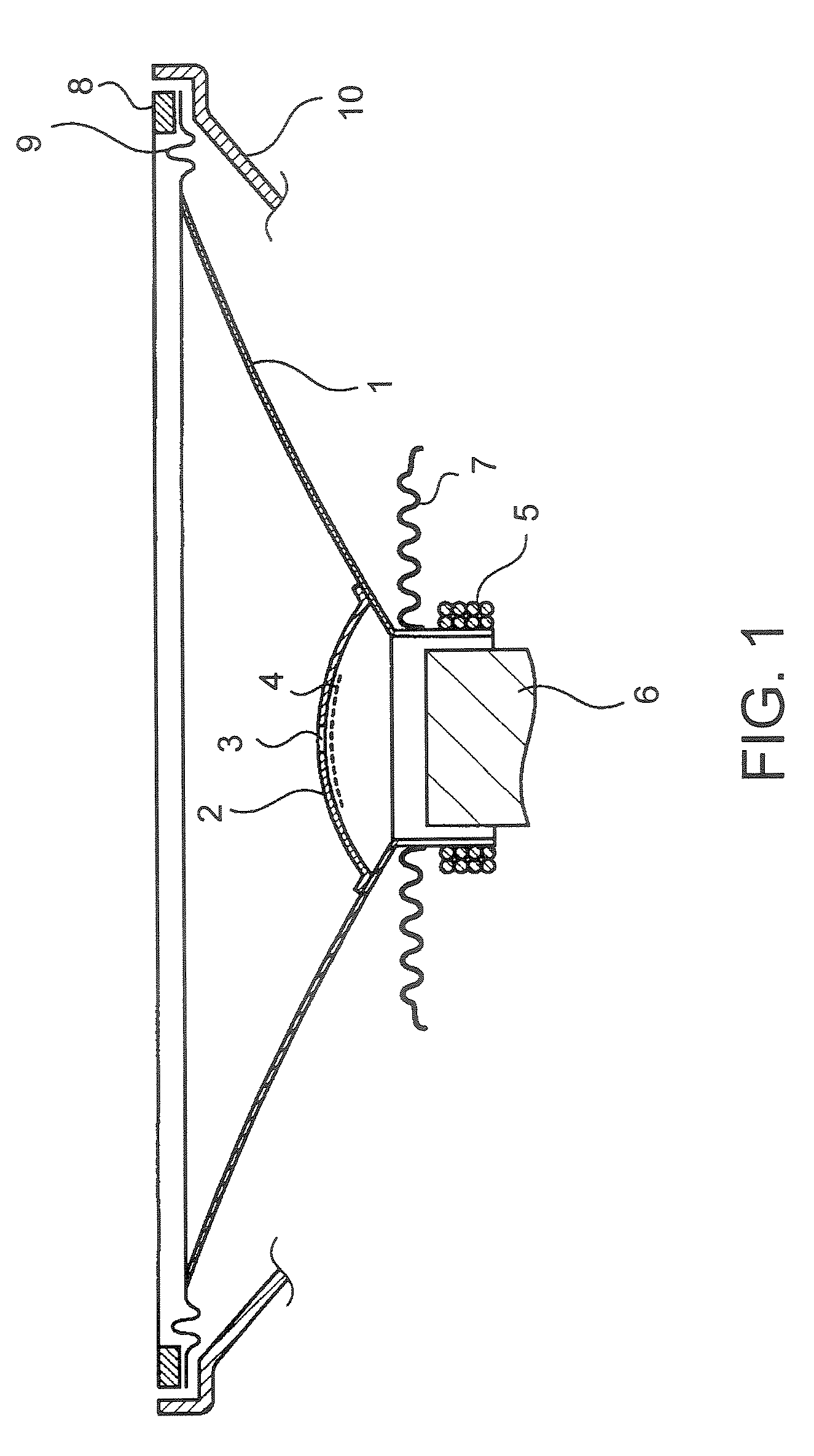
[0023]FIG. 1 is a drawing explaining vibration components of a loudspeaker. As shown in FIG. 1, a loudspeaker unit is configured as having the vibration components of loudspeaker. As in FIG. 1, it is necessary for a cone 1 which serves as a loudspeaker diaphragm, that it can be molded into a thin wall to be easily vibrated, that it is small in weight and tough, and that it can ensure an appropriate level of loss, called internal loss, for a purpose of reducing peaks and dips in the frequency characteristics and transient characteristics.

[0024]A center cap 2 is provided for purposes of preventing radial deformation of the cone 1, and of preventing iron powder or dust from coming into a gap. The center cap 2 has a hole 3 opened at around the center thereof, and the hole 3 is covered with a wide-mesh cloth 4. The hole 3 allows the air, compressed or expanded by means of vibration...


PUM


Abstract

There is provided an acoustic diaphragm used for a loudspeaker, having an injection-molded edge molded using a thermoplastic elastomer, in which the edge is formed using a workable polyolefinic elastomer, as a material, containing a soft segment having rubber particles of 1 μm to 10 μm in diameter uniformly dispersed therein, and a hard segment composed of an olefinic resin, and the edge is formed into a shape allowing the resin to be aligned as being not causative of anisotropy in the physical characteristics of the edge, as a result of thin-wall molding by the injection molding.

Description

BACKGROUND OF THE INVENTION[0001]1. Field of the Invention[0002]The present invention relates to an acoustic diaphragm having, as being fixed to the outer periphery thereof, a loudspeaker edge for controlling motion of the loudspeaker diaphragm, and a method of fabricating an acoustic diaphragm.[0003]2. Description of Related Art[0004]A cone-type loudspeaker generally has a mold edge composed of a rubber elastomer, as being fixed to the outer periphery of a diaphragm. It is necessary for the edge to damp motion at an excellent level, under continuous propagation of vibration by the diaphragm, so as to avoid influence mutually exerted on the previous and the next vibration transmissions. At the same time, it is also important for the edge to ensure a good linearity in compliance with the motion of the diaphragm, that is, an excellent flexibility.[0005]Among a large variety of materials having been used aiming at realizing these features, the most representative one is a vulcanized ru...

Claims


Application Information

Patent Timeline
Patent Type & Authority Patents(United States)
IPC IPC(8): H04R7/00H04R1/00
CPCH04R7/24H04R7/18H04R31/003H04R2307/025
Inventor TOKURA, KUNIHIKOURYU, MASARUTAKEBE, TORU
Owner SONY CORP
Why Eureka
Try Eureka