Surface acoustic wave sensor

a surface acoustic wave and sensor technology, applied in the direction of instruments, generators/motors, material analysis, etc., can solve the problem that the electrical conductivity of sensitive materials is not indispensable, and achieve the effect of improving the accuracy, improving the efficiency, and improving the accuracy

Inactive Publication Date: 2011-06-09
MURATA MFG CO LTD
View PDF4 Cites 2 Cited by
  • Summary
  • Abstract
  • Description
  • Claims
  • Application Information

AI Technical Summary

Benefits of technology

[0024]In various preferred embodiments of the present invention, at least a portion of the comb shaped electrode is electrically conductive and is made of the sensitive material which responds to the specific detection object or at least a portion of the reflector is made of the sensitive material which responds to the specific detection object. Therefore, the production steps can be simplified as compared with those of a surface acoustic wave sensor, in which a reaction film is disposed on the comb shaped electrode and the reflector. Consequently, variations in accuracy, which are accumulated in a plurality of production steps, become small. Furthermore, since the sensitive material acts directly on the piezoelectric substrate, a high-sensitivity surface acoustic wave sensor excellent in economy can be provided.

Problems solved by technology

According to this configuration, the electrical conductivity of the sensitive material is not indispensable.

Method used


Image

  • Surface acoustic wave sensor
  • Surface acoustic wave sensor
  • Surface acoustic wave sensor

Examples


first preferred embodiment

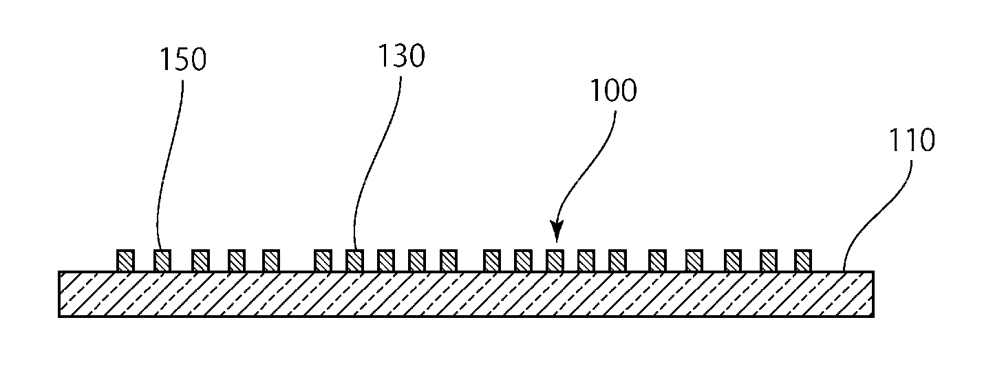
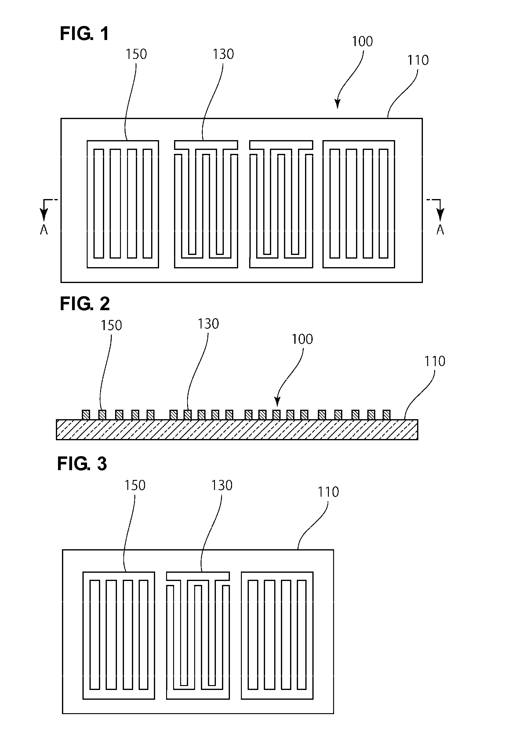
[0039]FIG. 1 is a schematic plan view of a 2-port resonator type surface acoustic wave sensor according to a first preferred embodiment of the present invention. FIG. 2 is a schematic sectional view showing the electrode structure along a line A-A shown in FIG. 1.

[0040]A surface acoustic wave sensor 100 shown in FIG. 1 and FIG. 2 is an apparatus which detects a specific detection object on the basis of a change in output signal. As shown in FIG. 1 and FIG. 2, the surface acoustic wave sensor 100 is preferably provided with a piezoelectric substrate 110 and four comb shaped electrodes 130 and one pair of grating reflectors 150 disposed on the piezoelectric substrate 110, for example. The four comb shaped electrodes constitute two comb shaped electrode pairs. Each comb shaped electrode pair constitutes an IDT electrode. The one pair of reflectors 150 are arranged to sandwich the two comb shaped electrode pairs. That is, the one pair of reflectors 150 are disposed on both sides of a re...

second preferred embodiment

[0058]FIG. 3 is a schematic plan view of a surface acoustic wave sensor according to the second preferred embodiment. In the above-described first preferred embodiment, the 2-port resonator type surface acoustic wave sensor is explained as an example. However, in the present invention, the surface acoustic wave sensor is not limited to the 2-port resonator type surface acoustic wave sensor. For example, as shown in FIG. 3, the surface acoustic wave sensor may be a sensitive material 1-port resonator type surface acoustic wave sensor.

third preferred embodiment

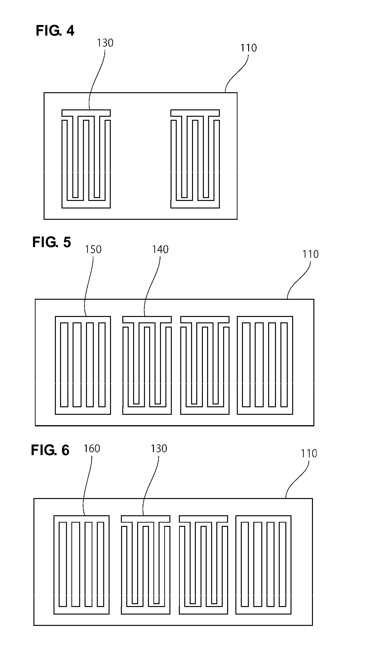
[0059]FIG. 4 is a schematic plan view of a surface acoustic wave sensor according to the third preferred embodiment. In the above-described first and second preferred embodiments, the surface acoustic wave sensors including the reflectors are explained as examples. However, the present invention is not limited to the surface acoustic wave sensor including the reflector. For example, as shown in FIG. 4, the surface acoustic wave sensor may be a so-called transversal type surface acoustic wave sensor, in which a propagation path is provided between two IDT electrodes composed of interdigitated two comb shaped electrodes 130.

Fourth and Fifth Preferred Embodiments

[0060]FIG. 5 is a schematic plan view of a surface acoustic wave sensor according to a fourth preferred embodiment of the present invention. Furthermore, FIG. 6 is a schematic plan view of a surface acoustic wave sensor according to a fifth preferred embodiment of the present invention.

[0061]In the above-described first to thir...


PUM


Abstract

A surface acoustic wave sensor is capable of detecting a specific detection object with high accuracy and is excellent in economy. The surface acoustic wave sensor includes a piezoelectric substrate and a comb shaped electrode disposed on the piezoelectric substrate to detect a specific detection object on the basis of a change in output signal. At least a portion of the comb shaped electrode is electrically conductive and is made of a sensitive material which responds to the above-described specific detection object.

Description

BACKGROUND OF THE INVENTION[0001]1. Field of the Invention[0002]The present invention relates to a surface acoustic wave sensor. In particular, the present invention relates to a surface acoustic wave sensor including a piezoelectric substrate and a comb shaped electrode disposed on the piezoelectric substrate to detect a specific detection object on the basis of a change in output signal.[0003]2. Description of the Related Art[0004]Various sensors using a surface acoustic wave have been proposed previously. For example, Japanese Unexamined Patent Application Publication No. 2005-331326 described below discloses a surface acoustic wave sensor 200 provided with a structure shown in FIG. 11 and FIG. 12.[0005]As shown in FIG. 11 and FIG. 12, the surface acoustic wave sensor 200 includes comb shaped electrodes 220 and reflectors 230 disposed on a piezoelectric substrate 210 and a reaction film 240, which is disposed on the comb shaped electrodes 220 and the reflectors 230, which reacts ...

Claims


Application Information

Patent Timeline
Patent Type & Authority Applications(United States)
IPC IPC(8): H01L41/00
CPCG01N29/022G01N29/036G01N29/2462H01L41/1132G01N2291/0256G01N2291/0423G01N2291/0255H10N30/302
Inventor ITO, SHIGEOKADOTA, MICHIOITO, YOSHIHIROHOSHINO, YURI
Owner MURATA MFG CO LTD
Why Eureka
Try Eureka