Lubricating system for a vehicle transmission component, vehicle therewith, and method of lubricating a transmission component

a technology of transmission components and lubricating systems, which is applied in the direction of gearing control, gearing lubrication/cooling, gearing elements, etc., can solve the problems of dragging on the ring gear, inefficiency relating to churn loss, and high energy loss, so as to reduce the loss of bearing spin and high energy loss. , the effect of high energy loss

Inactive Publication Date: 2018-03-01
JAGUAR LAND ROVER LTD
View PDF3 Cites 8 Cited by
  • Summary
  • Abstract
  • Description
  • Claims
  • Application Information

AI Technical Summary

Benefits of technology

[0021]The supply line may be arranged to direct lubricant to a pinion bearing, a differential case bearing, or a pinion / ring gear mesh point of the final drive gear. These points are all associated with high energy losses since there is frictional contact between mutually moving parts. In particular, pinion bearings are associated with very high energy losses when not targeted. Targeting the pinion bearings reduces bearing spin loss and dramatically reduces the associated energy losses of the transmission system.
[0022]The controller may be arranged to detect the actual flow-rate of lubricant through the supply line and may emit a warning if the actual flow rate falls below an acceptable actual flow rate of lubricant. Such a warning can serve to warn the driver that there are irregularities within the transmission system, or lubricating system such as clogging of a filter. In addition, the warning may serve to restrict vehicle performance so as to prevent lubricant starvation, for instance in the cases of maximum power or maximum speed.

Problems solved by technology

However, such wet sump configurations are fraught with inefficiencies.
One inefficiency relates to churn loss as the ring gear rotates through the lubricant causing drag on the ring gear.
In addition, especially at cold temperatures when the lubricant is highly viscous, the lubricant exiting the bearings is slowed down resulting in the bearings becoming flooded, which causes increased shearing forces across the lubricant.
However, when the bearings become flooded, bearing spin loss increases.
Such a system aids with reducing gear churn losses but does little to improve bearing spin loss.

Method used


Image

  • Lubricating system for a vehicle transmission component, vehicle therewith, and method of lubricating a transmission component
  • Lubricating system for a vehicle transmission component, vehicle therewith, and method of lubricating a transmission component
  • Lubricating system for a vehicle transmission component, vehicle therewith, and method of lubricating a transmission component

Examples


Embodiment Construction

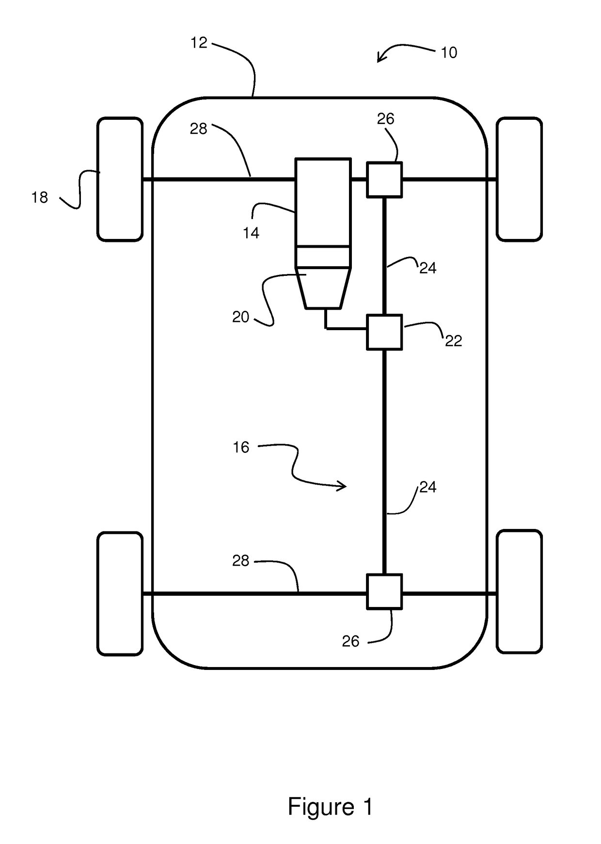
[0043]With reference to FIG. 1, a vehicle 10, such as a car or other land vehicle, includes a chassis 12 supporting an engine 14 and a transmission and / or a driveline system 16 transmitting power from the engine to the wheels 18. Reference to the transmission and / or driveline system is hereinafter described as the transmission system. In this instance there are four wheels 18, all of which are driven wheels since this this vehicle 10 is embodied as a four wheel drive vehicle.

[0044]The transmission system 16 includes various transmission components including a gear box 20, a transfer drive unit 22, fore and aft drive shafts 24, fore and aft final drive units 26, or colloquially, differentials, and front and rear side shafts 28. The fore and aft ends of the drive shaft 24 are connected to front and rear final drive units 26. The differentials 26 are connected to front and rear side shafts 28 which in turn are connected to near side and off side wheels 18. The differentials 26 are used...


PUM


Abstract

The present invention relates to a lubricating system for a vehicle transmission component. The system comprises a lubricating circuit (44) for supplying lubricant to a transmission component, the circuit (44) including a reservoir (46), a supply path for supplying lubricant from the reservoir (46) to the transmission component, and a return path for returning lubricant from the transmission component to the reservoir (46). The system also comprises an electrical pump (52) for pumping lubricant from the reservoir (46) to the transmission component and a controller (56) arranged to monitor a driving condition and configure the electrical pump (52) to pump a predetermined flow rate of lubricant to the transmission component based on the current driving condition.

Description

TECHNICAL FIELD[0001]The present disclosure relates to a lubricating system and particularly, but not exclusively, to a lubricating system for a transmission component of a vehicle such as a land vehicle. Aspects of the invention relate to a lubricating system for a transmission component of a vehicle, a vehicle, and a method of lubricating a transmission component of a vehicle.BACKGROUND[0002]A vehicle, such as a car or the like, includes various rotating components. Typical rotating components include those forming a transmission and driveline system of the vehicle including a gear box and a final drive gear. Such transmission and driveline systems are referred to hereinafter as transmission systems. Such components require lubrication to reduce wear and reduce temperature in-use.[0003]Vehicles typically employ a lubricating system for lubricating the transmission components. Known lubricating systems come in two general configurations; firstly a wet sump configuration or, secondl...

Claims


Application Information

Patent Timeline
Patent Type & Authority Applications(United States)
IPC IPC(8): F16H57/04
CPCF16H57/0409F16H57/0405F16H57/0436F16H57/0469F16H57/0483F16H57/0495F16H57/045F16H59/14F16H59/34F16H59/44F16H59/72F16H61/0021F16H57/0434F16H57/0435F16H57/0443F16H57/046F16H2059/663F16H2061/0037F16H57/0447F16H57/0449
Inventor OSBORN, RUSSELLFOSTER, JAIMIE
Owner JAGUAR LAND ROVER LTD
Why Eureka
Try Eureka