
Lighting device

a technology of lighting device and light source, which is applied in the direction of lighting and heating apparatus, instruments, non-linear optics, etc., can solve the problems of not providing illumination that imitates natural light, and not providing a lighting environment resembling the natural environmen

Active Publication Date: 2018-03-01
PANASONIC INTELLECTUAL PROPERTY MANAGEMENT CO LTD
View PDF4 Cites 2 Cited by
  • Summary
  • Abstract
  • Description
  • Claims
  • Application Information

AI Technical Summary

Benefits of technology

The patent describes a way to recreate a lighting environment that mimics the natural environment. This technology can make it easy to recreate the kind of lighting that was found in certain locations, providing a more authentic and realistic experience for users.

Problems solved by technology

Thus, the conventional lighting device does not provide illumination that imitates the natural light, and cannot provide a lighting environment resembling the natural environment.

Method used


Image

  • Lighting device
  • Lighting device
  • Lighting device

Examples


embodiment 1

Variation of Embodiment 1

[0073]Hereinafter, lighting device 1 according to the present variation of Embodiment 1 will be described.

[Configuration]

[0074]Hereinafter, the configuration of lighting device 1 according to the present variation of Embodiment 1 will be described.

[0075]The present variation of Embodiment 1 is different from Embodiment 1 in that while the image light with which light-transmissive plate 3 is irradiated in Embodiment 1 includes the image light in the first wavelength range and the image light in the second wavelength range, the image light, with which light-transmissive plate 3 is irradiated in the present variation of Embodiment 1 includes light in the first wavelength range and the image light in the second wavelength range.

[0076]The other elements of lighting device 1 in the present variation of Embodiment 1 are the same as those of lighting device 1 in Embodiment 1; identical reference signs are given to identical elements, and detailed descriptions of suc...

embodiment 2

[0086]Hereinafter, lighting device 100 according to the present embodiment will be described.

[Configuration]

[0087]The configuration of lighting device 100 according to the present embodiment will be described with reference to FIG. 6 and FIG. 7.

[0088]FIG. 6 is a schematic cross sectional view of lighting device 100 according to the present embodiment. FIG. 7 is a block diagram illustrating lighting device 100 according to the present embodiment.

[0089]The present embodiment is different from Embodiment 1 in that image projecting device 4 in the present embodiment includes reflector plate 140 that oscillates and oscillator 130.

[0090]The other elements of lighting device 100 in the present embodiment are the same as those of lighting device 1 in Embodiment 1. Identical reference signs are given to identical elements, and detailed descriptions of such elements will be omitted.

[0091]As illustrated in FIG. 6 and FIG. 7, lighting device 100 includes oscillator 130 and reflector plate 140 a...


PUM

PropertyMeasurementUnit
color temperatureaaaaaaaaaa
wavelengthaaaaaaaaaa

Abstract

A lighting device is provided. The lighting device includes: a light-transmissive plate having an entrance surface; and an image projecting device that irradiates the entrance surface of the light-transmissive plate with image light. The image light passing through the light-transmissive plate is projected on an object. The image light emitted by the image projecting device includes light in a first wavelength range and light in a second wavelength range. Here, the light in the second wavelength range is longer in wavelength than the light in the first wavelength range. The light-transmissive plate absorbs or scatters the light in the first wavelength range more than the light in the second wavelength range.

Description

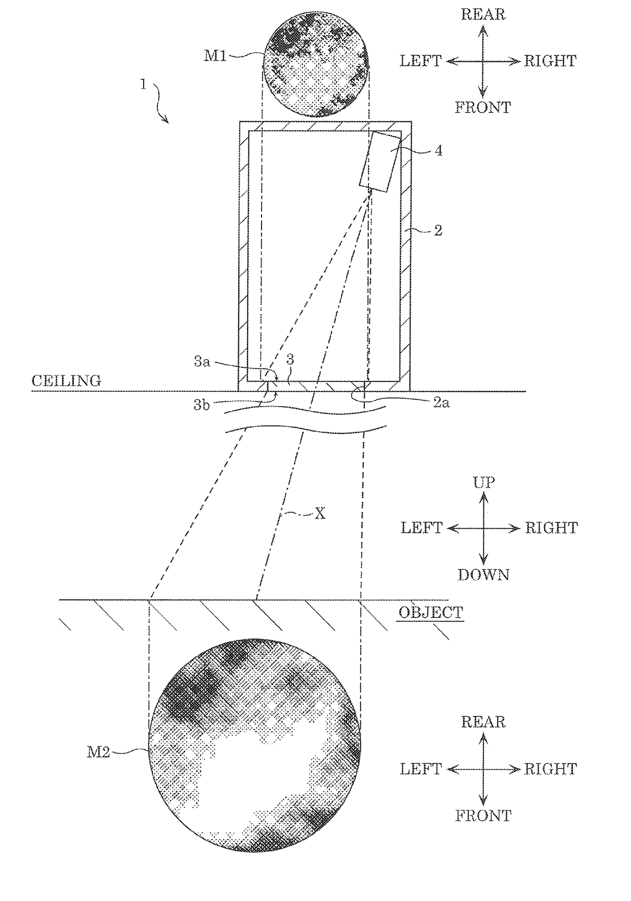
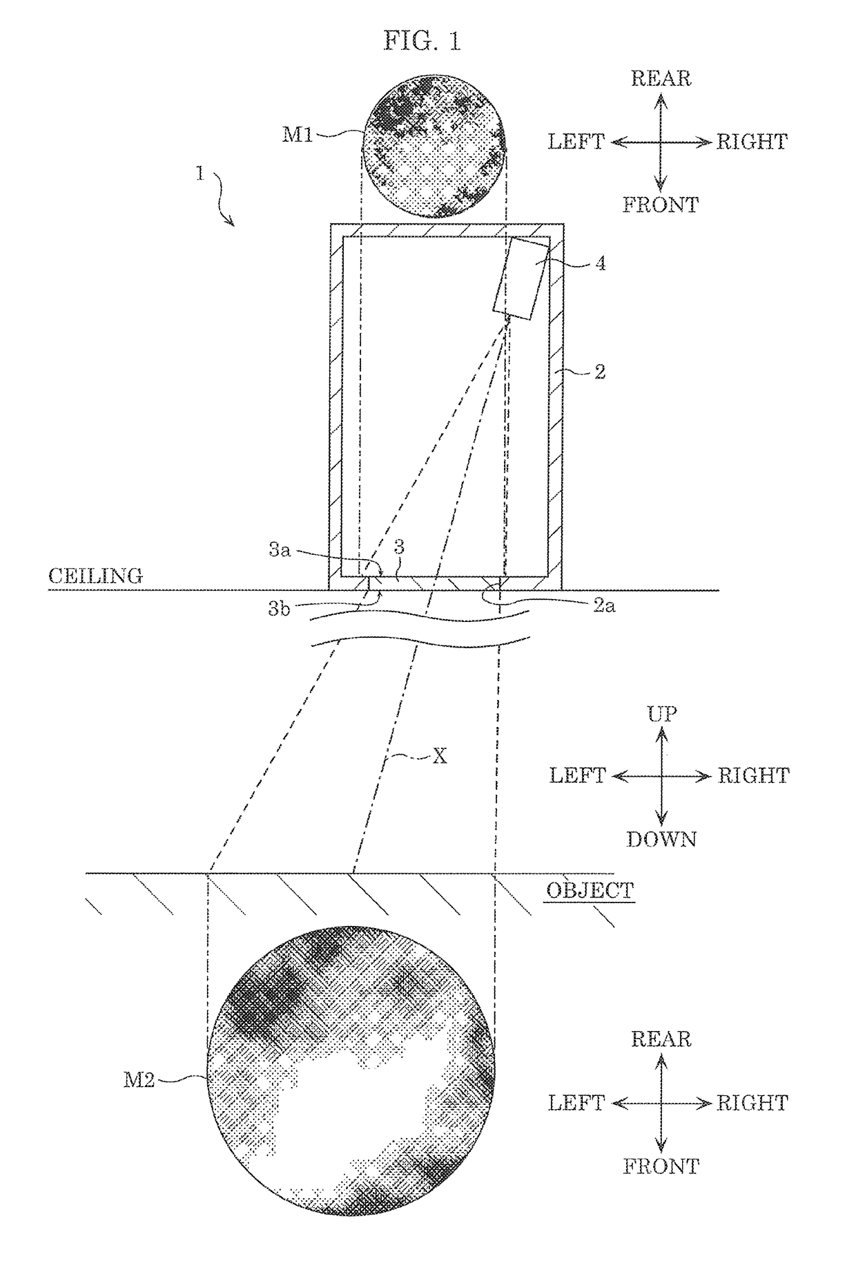
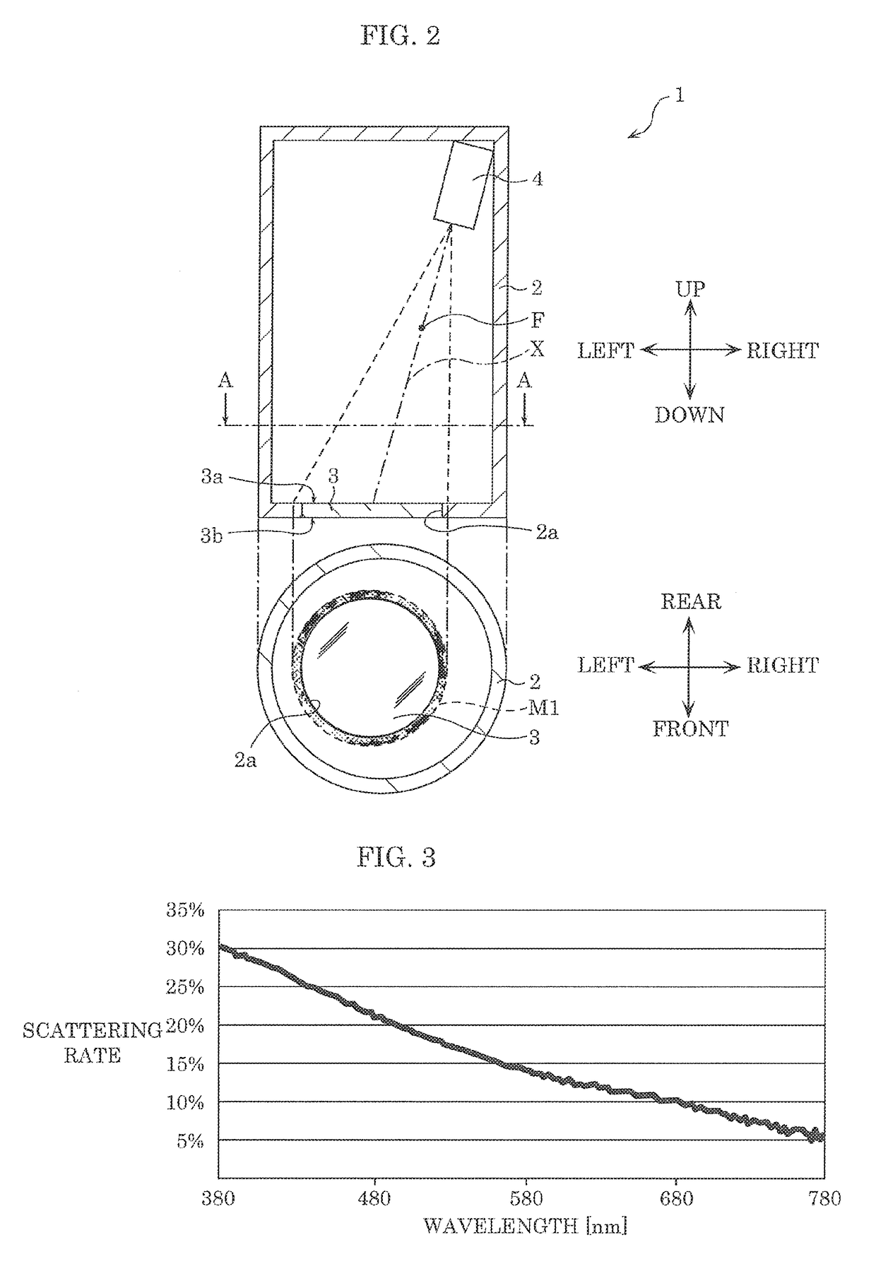
CROSS REFERENCE TO RELATED APPLICATION[0001]This application claims the benefit of priority of Japanese Patent Application Number 2016-168606 filed on Aug. 30, 2016, the entire content of which is hereby incorporated, by reference.BACKGROUND1. Technical Field[0002]The present disclosure relates to a lighting device.2. Description of the Related Art[0003]Conventionally, a lighting device including a liquid crystal panel that emits image light, a liquid crystal display device that displays an image, and an image generation means that generates an image is disclosed (see Japanese Unexamined Patent Application Publication No. 2013-92616 (Patent Literature (PTL) 1), for example).[0004]This lighting device creates a lighting environment into which light streams, by the liquid crystal display device displaying an image.SUMMARY[0005]With the lighting device disclosed in PTL 1, however, the same image as that generated by an image projecting device is projected on an object when the object i...

Claims


Application Information

Patent Timeline
Patent Type & Authority Applications(United States)
IPC IPC(8): G02F1/1335G02F1/13
CPCG02F1/13G02F1/133512G03B21/206G03B21/2066G09F19/18G03B21/001F21V9/02G02F1/133514
Inventor YAMAUCHI, KENTARO
Owner PANASONIC INTELLECTUAL PROPERTY MANAGEMENT CO LTD
Features
  • Generate Ideas
  • Intellectual Property
  • Life Sciences
  • Materials
  • Tech Scout
  • Unparalleled Data Quality
  • Higher Quality Content
  • 60% Fewer Hallucinations
Learn More