Method of Forming a Rarefied Hologram for Video Imaging and 3D Lithography
Inactive Publication Date: 2018-06-21
YANKOV VLADIMIR +2
1 Cites 0 Cited by
AI-Extracted Technical Summary
Problems solved by technology
Normally, the formation of such remote virtual 3D image by holographic methods requires a large number of calculations performed by a computer.
The number of ...
Benefits of technology
[0022]Thus, it becomes possible to reproduce the complete image by utilizing onl...
Abstract
A method of forming a rarefied hologram for video imaging and 3D lithography by using an MEMS/SLM with a plurality of pixels on the surface at a fixed distance from the retina of the viewer′ eye. The method consists of providing an initial desired image, which has to be holographically reproduced by the MEMS/SLM as a remote virtual 3D image visible by the viewer's eye. The desired image is coded in a special manner and mapped by encoding and calculating only a part of the initial desired image. The operations of the pixels are controlled in accordance with the code for generation of the holographic pattern. Since only a part of a holographic pattern of the image is encoded and calculated, it becomes possible to reduce the calculation time and decrease parasitic light scattering.
Application Domain
Holographic light sources/light beam propertiesHolographic optical components +2
Technology Topic
3d imageLithography +3
Image
Examples
- Experimental program(1)
Example
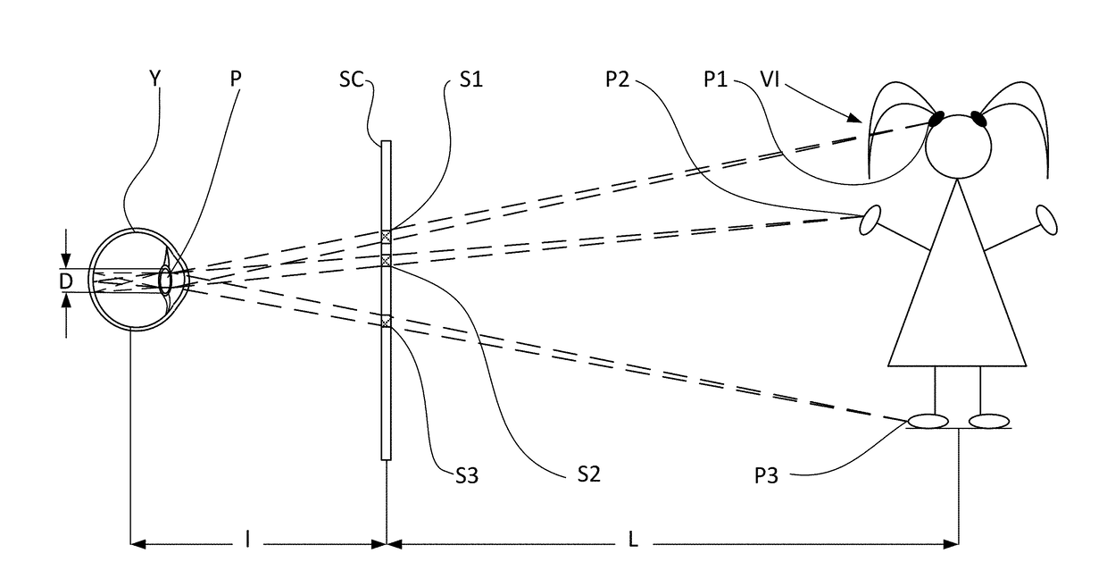
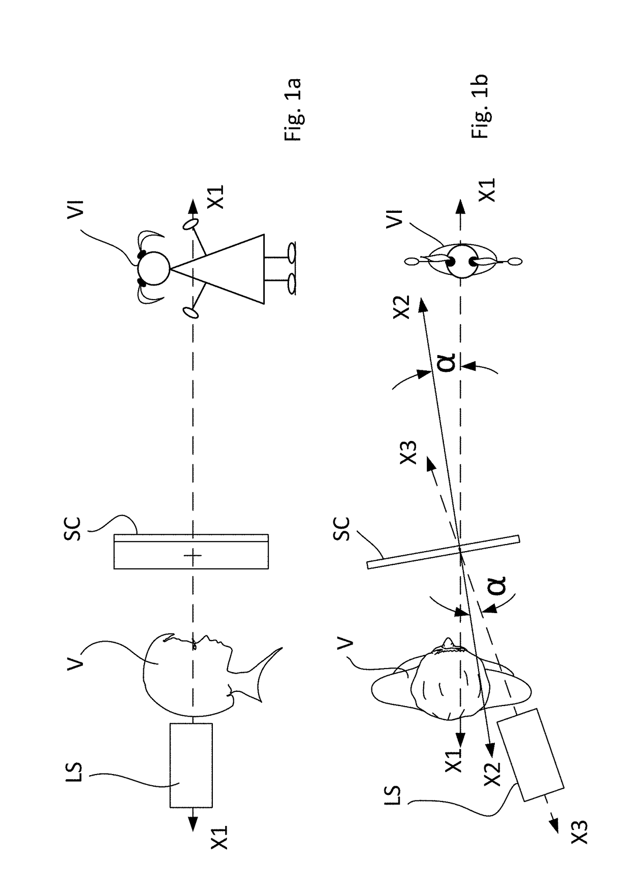
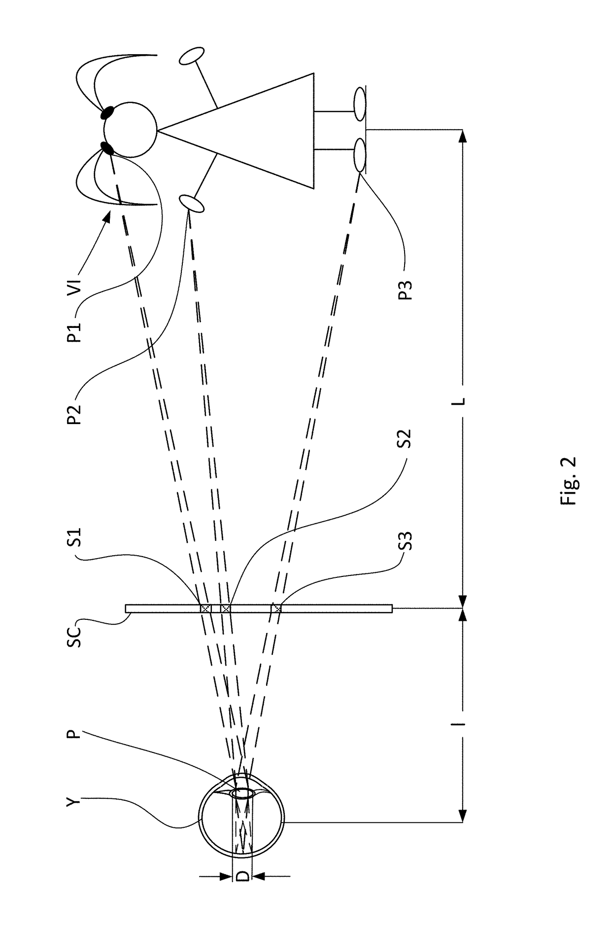
[0034]This invention relates to a novel method of forming so-called rarefied holograms for video Imaging and 3D lithography. This concept of a rarefied hologram presented herein is entirely new and has been developed for the first time by the applicants. More specifically, the rarified holograms mean holograms that contain a reduced number of holographic elements and therefore possesses a “density” lower than conventional holograms that used for achieving the same results.
[0035]In other words, the invention also relates to dynamically processing coherent light for obtaining computer-generated holograms, which include elements the number of which is from ten to hundred times fewer than the number of elements from which conventional holograms are formed. This technology is applicable to 3D displays and 3D lithographers and is capable to create clear holographic virtual images which are free of so-called “ghosts” and characterized by reduced noise.
[0036]The method of the present invention for the formation of a rarefied hologram will now be described with reference to FIGS. 1a and 1b, where FIG. 1a is a schematic side view of an optical system that illustrates the principle of the invention, and FIG. 1b is a top view of the objects shown in FIG. 1a.
[0037]More specifically, FIGS. 1a and 1b illustrate an optical system in which a rarefied pixilated virtual image can be created. The reference symbol LS designates a coherent laser source, V is a viewer, SC is a non-transparent active screen the structure of which will be described later, and VI is a virtual image, which in this case constitutes a virtual hologram seen by the viewer V.
[0038]FIG. 2 is a schematic side view that illustrates the principle used for rarefication of a pixelated virtual image in accordance with the present invention.
[0039]For simplicity of the explanation the optical system is shown for one eye of the viewer. However, the same principle is applicable for viewing a virtual image simultaneously with two eyes. In FIG. 2, the parts of the screen designated as S1, S2, and S3 correspond to certain points P1, P2, and P3 of the holographic image VI for generation of which these parts of the screen are responsible. It should be noted that in reality each point belongs to a certain area of the image. These areas are arranged discretely on a predetermined surface and in fact comprise parts of the rarefied hologram while in combination they reproduce the entire holographic image. Each part of the screen such as parts S1, S2, S3, etc. may contain a large number of pixels, e.g., 100, 200, . . . 1000 pixels, or more.
[0040]It is important to note that in the optical system of the invention a distance from the screen SC to the pupil P of the viewer's eye Y (FIG. 2) must be constant. This condition can be fulfilled, e.g., by installing the screen SC on a head-wearable device such as a helmet (not shown).
[0041]The screen SC is an active non-transparent screen that creates on the retina of the eye an image. The screen has a plurality of pixels comprising independently working and individually controllable light-emitting elements, and the term “active” means that the image is created by reflection from these pixilated light emitting elements.
[0042]As can be seen from FIG. 1b, the screen SC may be turned at a certain angle α with respect to an axis X1-X1 that comprises an optical axis of the eye Y. In this case, the optical axis X3-X3 of the light source SC is turned at angle α to the optical axis of the screen SC. The axis X2-X2 is a perpendicular to the screen SC. All three axes X1-X1, X2-X2 and X3-X3 are coplanar.
[0043]The invention is based on the principle of dynamically processing a light coded with a phase shift keying in holograms, where emitters are much bigger than holographic fringes. FIG. 3a is a view of a part of a non-transparent screen illustrating random arrangement of microilluminators that are in the pixels of the screen SC when the MEMS/SLM is illuminated with a laser light beam. FIG. 3b is a sectional view along line IIIb-IIIb of FIG. 3a.
[0044]As can be seen from FIGS. 3a and 3b, each pixel of the screen SC is covered with a group of Fresnel lenses such as lenses FL1, FL2, FL3, . . . FLn. It can also be seen from FIG. 3b that each lens moveable in its respective pixel in accordance with coding of the image. It is important to note that for the rarefication principle of the invention the center points of the Fresnel lenses must be randomly arranged in the pixels of the screen.
[0045]To increase the reception angle of a hologram viewer, the cross-section size of the emitted beams on the outer surface of the pupil should be much smaller than the size of the emitters. This means that the size of the pixel is much greater than the size of a focal spot formed by the Fresnel lens (see FIG. 7).
[0046]The positions of the beams are randomized to suppress the ghost reflections which could occur in case of a regular arrangement of the emitter centers. The invention is a true also for 3D displays, which may be head mounted to show augmented and artificial reality video. A head mounted display will benefit from accurate positioning with respect to human pupils and restoration of the wave front at the surface of the pupils only, which greatly increases hologram performance and lowers restrictions on hardware.
[0047]One implementation is a conventional MEMS display with additional structures placed on each pixel, which makes beams with smaller focus, see FIG. 3b. The ghost images may be suppressed by placing the Fresnel lenses on the mirrors of the MEMS system in a randomized manner.
[0048]Simulations of the ghost suppression are presented on FIGS. 4-6. These pictures show simulation of noise as a function of pixel pitch as well as suppression of ghost reflection by randomizing placing of the pixels. FIG. 4 shows simulated visible optical field (square root of the intensity). The visible plane is 10 m from the viewer, in reality there are 7 light point sources on a black field. This picture is a reconstruction visible in a 10×10 mm display composed of 32×32 pixels with randomized locations (1024 pixels in total). The simulated area is 40×40 mm (at 10 m from the viewer).
[0049]FIG. 5 also shows simulation of multiple ghost reflections of a seven-point picture. Conditions of observation are the same as in FIG. 4, but the display is now 320×320 pixels. We can observe much higher signal-to-noise ratio.
[0050]FIG. 6 shows simulation under the same condition as in FIG. 4, but the pixels are placed in a regular grid. Although the signal-to-noise is good, each light source is repeated as a ghost placed on a grid with approximately 17 mm steps (diffraction pattern from the pixel grid).
[0051]The method of coding of originals images with a hologram is an important part of the invention. In particular, there is a mapping of the image on the display (see FIG. 2), which allows calculating to be made only for a part of a holographic pattern of an image on the display. This saves the calculation time and decreases a parasitic light scattering. For example, an image of the girl's hand (point P2 in FIG. 2) is encoded only for the part S2 of the screen SC located between the hand and the pupil P of the eye, as shown by dashed lines.
[0052]The mapping procedure may be performed as described below. Let us assume that the coherence length of the light source LS is equal to or greater in diameter than the diameter D of the pupil P (see FIG. 2). Let us also assume that a virtual image that has to be generated has predetermined horizontal and vertical angular dimensions.
[0053]By connecting the extreme points of the virtual image with the point on the eye that limit the aperture of the eye pupil (as shown in FIG. 2), we obtain a tapered space in which a wavefront that must form the virtual image should propagate in the direction toward the eye Y. This wavefront may be generated by a reflective MEMS/SLM of a matrix type which changes phases of the light reflected from the pixels. Let us place such a modulator SC between the viewer's eye Y and the virtual image VI. For example, if we use an 8-bit reflective spatial matrix-type modulator with an active area of 25.6 mm×15.4 mm with a pixel pitch of 20 μm and with a resolution capacity of 1280×768 and divide the modulator into regular fragments, e.g., 10×10 pixels in each fragment, then we obtain about 104 of such fragments. The hologram that is created in the above case by these 104 points is a rarefied hologram obtained by the method of the invention. It is understood that 104 points were given only as an example.
[0054]If we project lines from the extreme point of the pupil through the aforementioned fragments to respective points on the object, we will obtain about 104 points which will present the virtual object VI in the viewer's eye.
[0055]It is understood, as we mentioned above, that the pixels of the reflective spatial matrix-type modulator should be coated with reflective Fresnel lenses (see FIGS. 3a and 3b).
[0056]The 8-bit reflective spatial matrix-type modulator with an active area of 25.6 mm×15.4 mm with a pixel pitch of 20 μm and with a resolution capacity of 1280×768 was given only as an example, and modulators, e.g., with high resolution such as 1280×1024, etc., as well as modulators with other pixel pitches, etc. also can be employed.
[0057]The pupil surface can be illuminated with beams having a coherence length smaller than the size of the pupil, whereby it is possible to effectively subdivide the original image, the display, and the parts of the outer pupil surface into small interconnected fragments, which is shown on FIG. 7. In this case, the pupil will be divided into smaller parts PP1, PP2, . . . PPn. These parts correspond to coherent length of a light source LS and the display fragmentation S1, S2, . . . Sn (FIG. 2) corresponds to these smaller parts PP1, PP2, . . . PPn of the outer pupil surface. Light beams generated by display SC fragments S1, S2, . . . Sn are designated as BS1′, BS2′, . . . BSn′.
[0058]In FIG. 1b it is shown that the screen SC is arranged in a position in which its surface is not perpendicular to the eye axis XI-XI. With this arrangement, the beams reflected from screen to the eye in a zero order (an incident angle is equal to the reflection angle). However, the screen may be oriented perpendicular to the eye axis. In this case, a direction of the incident light should be selected so that it would be possible to provide entering the eye of the reflected beams of the first or another highest order.
[0059]Since a head mounted device may have left and right displays for left and right eyes, respectively, it is important to encode in left and right holograms the binocular parallax matching the distance of the respective part of the image to the respective eye.
[0060]The principle of the invention is applicable to any displays that can be coded as holograms. For example, this can be a display in the form of a conventional on/off LCD matrix, where pixels with desirable phases can be simply switched on and off. It is understood that the noise will be smaller if at least 50% of the pixels are switched off. Another implementation is an MEMS/SLM, where phases are shifted and the phase shift, in turn, can be subdivided into 4, 8, 16 or even 256 positions. One more implementation may be a MEMS/SLM mirror matrix with two positions separated by a quarter of the wavelength of the laser light or with 4, 8, 16 or even 256 positions.
[0061]Coding the positions of the mirrors that should correspond to the rarefied target image is based on the phase of a beam generated by the respective mirror in the pupil of the viewer eye. This phase is chosen to approximate the wave front function w (x,y) which is determined by the following formula:
w(x,y)=Σn,mƒin(x,y)ƒout(x,y)
where ƒin(x,y) is the wave delivered by laser, ƒout(x,y) is the content wave to be restored by the display and observed by the viewer, where
f in ( x , y ) ≅ ∑ n C n exp ( ik r n ) f out ( x , y ) ≅ ∑ m C m exp ( - ik r m ) ,
where k is a wave vector, and rm is the distance to certain current image point m.
[0062]The phase of binary shifted emitters is calculated by approximating the aforementioned wave front function at the emitting point by formula: Pi=sign W(x,y) where x, y are coordinates of the emitter center.
[0063]Alternatively, the phase of discretely shifted emitters is calculated by approximating the above wave front function at the emitting point by using a phase nearest to w(x,y) where x, y are coordinates of the emitter center.
[0064]To suppress the speckles many frames per second may be encoded with different phases of original image, resulting in effective averaging of brightness variations.
[0065]FIG. 8 illustrates relationship between the pupil of a viewer's eye, a part of the screen that generates a virtual image (hologram), and the virtual image (rerified hologram). In this drawing, P′ designates a pupil of the viewer's eye which is shown schematically. Symbol PSC designated a part of the screen SC (FIG. 2). It should be noted that the parts S1′, S2′, S3′ . . . Sn′ (FIG. 8) of the screen SC (FIG. 2) are responsible for reproducing discrete parts PRH1, PRH2, PRH3. . . PRHn of the portion PRH of the virtual image VI on the rarefied hologram (FIG. 2). It can be seen that the discrete parts S1′, S2′, S3′ . . . Sn′ do not cover the entire surface of the virtual image and therefore the virtual image reproduced by such discrete parts is named as a rarefied hologram.
[0066]Note, that any change in the size or design of hologram-based displays will require recalculation of the phases. Calculations are faster if the image has a low information capacity like an augmented reality, consisting from several points, arrows, or lines. Holographic encodings of the lines, points or other sample images can be stored in a computer library and used without extensive calculations.
[0067]Although the invention has been described and illustrated with reference to the specific description and drawings, it is understood that any changes and modifications are possible without deviation from the scope of the attached claims. For example, the laser light can be modulated by means of liquid crystal. The modulation of light can be confined by using optical planar ridge waveguides. The light can be modulated by using a ferroelectric material. The phase shifts can be approximated by means of an on/off LC matrix. The pixels can be provided with additional features for maintaining the size of emitted beams much smaller than the size of the emitting spots. Additional features can be used for focusing gratings etched on the surface of the piston mirrors of the MEMS. The additional features may comprise static focusing gratings that direct the light to piston mirrors. The additional features may comprise static focusing gratings that direct the light to an LC matrix. It is also possible to measure the phase shifts of emitters caused by manufacturing inaccuracies and to take into account the determined inaccuracy in calculation of the wave front function. Focusing features of the MEMS in the form of Fresnel lenses may be replaced by holographic lenses etched on the pixel surfaces.
PUM


Description & Claims & Application Information
We can also present the details of the Description, Claims and Application information to help users get a comprehensive understanding of the technical details of the patent, such as background art, summary of invention, brief description of drawings, description of embodiments, and other original content. On the other hand, users can also determine the specific scope of protection of the technology through the list of claims; as well as understand the changes in the life cycle of the technology with the presentation of the patent timeline. Login to view more.
Similar technology patents
System for recognizing and validating banknotes
InactiveUS20040044626A1possible to reproduce
Owner:INVESTRONICA SA
Data recording device, data recording method, data reproducing device and data reproducing method
InactiveUS7024435B2possible to reproduce
Owner:SONY CORP
Classification and recommendation of technical efficacy words
- possible to reproduce
Data recording device, data recording method, data reproducing device and data reproducing method
InactiveUS7024435B2possible to reproduce
Owner:SONY CORP
System for recognizing and validating banknotes
InactiveUS20040044626A1possible to reproduce
Owner:INVESTRONICA SA