
Finger Joint Router Jig

a finger joint and router technology, applied in the field of wood working jigs, can solve the problems of creating a lot of offal material, no common standard for re-purposing or re-cycling this material, and inaccurate process

Active Publication Date: 2018-03-08
SAYLOR SOLUTIONS LLC
View PDF1 Cites 4 Cited by
  • Summary
  • Abstract
  • Description
  • Claims
  • Application Information

AI Technical Summary

Benefits of technology

The present disclosure describes a router jig that can simultaneously create finger joint grooves on two boards. The jig includes a base with two board guides and a router guide. The boards are clamped securely within the guides. The technical effect of this invention is that it allows for faster and more efficient finger jointing on multiple boards.

Problems solved by technology

Due to room sizes this creates a lot of offal material.
There is no common standard for re-purposing or re-cycling this material.
This process is very inaccurate and test pieces need to be routed to gauge accuracy.
This second method is time and material consuming process that is very cumbersome and lacks accuracy.

Method used


Image

  • Finger Joint Router Jig
  • Finger Joint Router Jig
  • Finger Joint Router Jig

Examples


Embodiment Construction

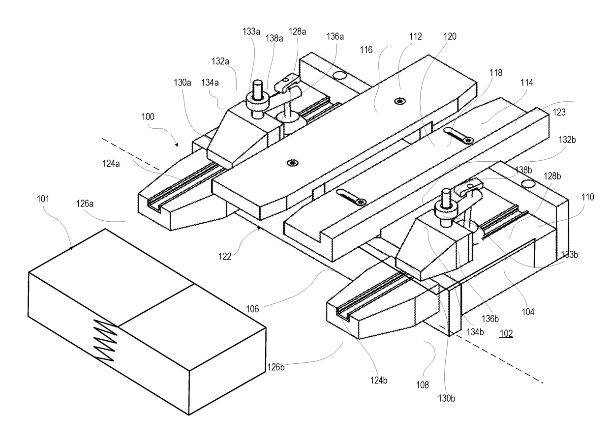
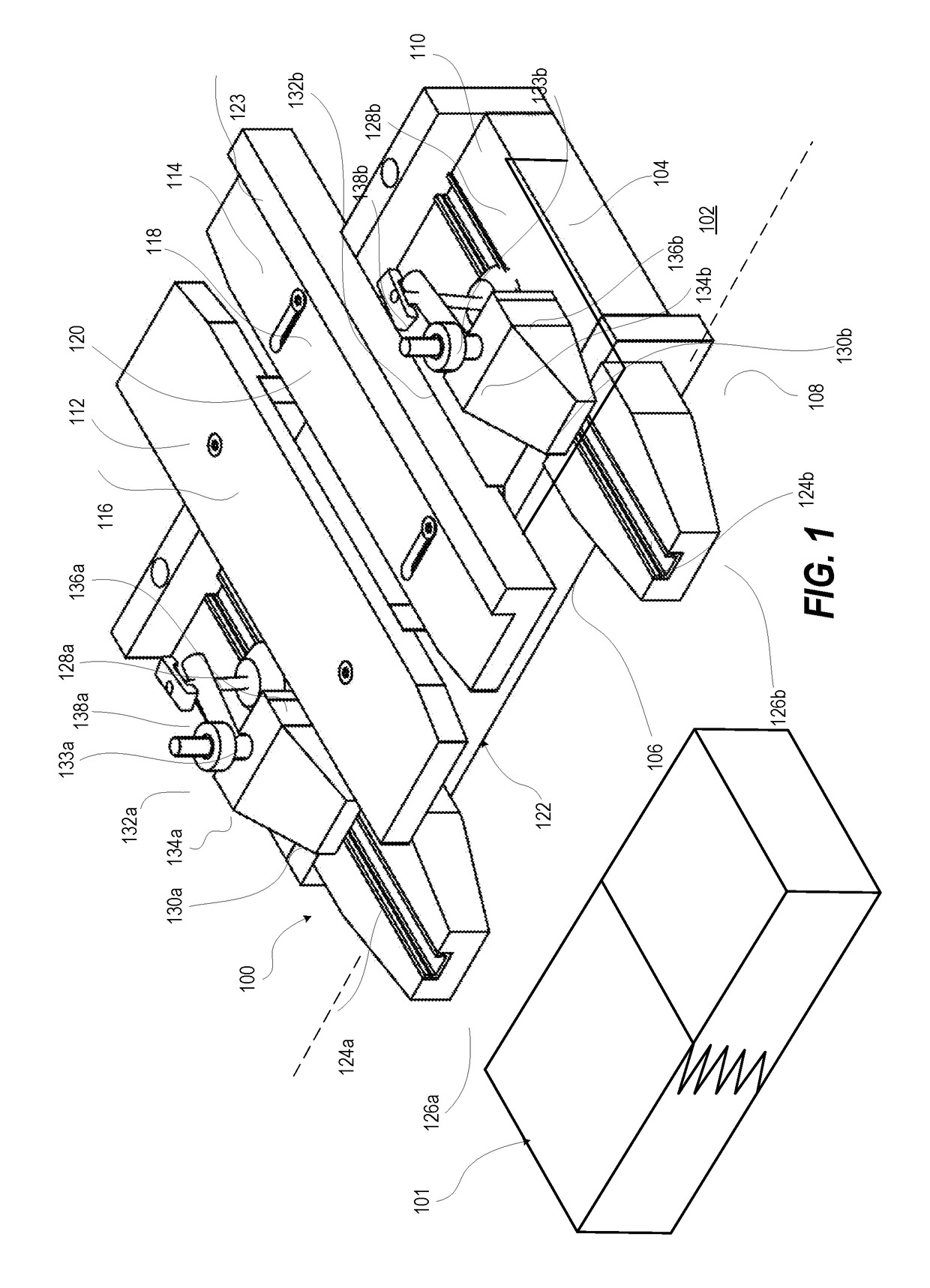
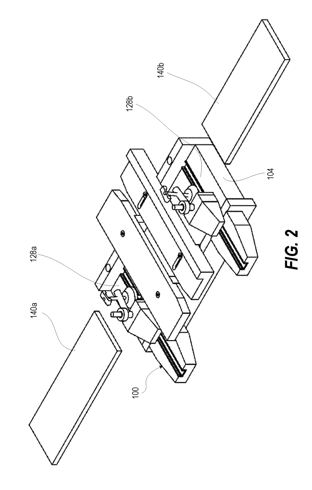
[0018]According to the present disclosure, a router jig is designed to mount on a work bench. Two pieces of trim molding are inserted from each end, meeting in the middle of the router jig. Then a clamping mechanism is engaged, securing the two pieces of trim molding in place. A hand held router with a finger joint bit installed is slid across a guide of the router jig, simultaneously routing the two pieces of molding trim to create a perfectly matched finger joint. Any variation in router speed, movement by operator, or other anomaly will still result in a matched finger joint due to the simultaneous and identical treatment of both pieces of trim molding.

[0019]References within the specification to “one embodiment,”“an embodiment,”“embodiments”, or “one or more embodiments” are intended to indicate that a particular feature, structure, or characteristic described in connection with the embodiment is included in at least one embodiment of the present disclosure. The appearance of su...


PUM


Abstract

A router jig includes a router jig base having: (i) a first board guide that receives an end of a first board; (ii) a second board guide that receives an end of an aligned second board from an opposite side; and (iii) a router guide that receives an guides a finger joint tool of a hand router along a transverse direction to the first and second board guides to simultaneously impart finger joint grooves. A clamping mechanism selectively clamps the first and second boards respectively within the first and second board guides.

Description

CLAIM OF PRIORITY UNDER 35 U.S.C. §119[0001]The present Application for Patent claims priority to Provisional Application No. 62 / 495,157 entitled “Finger Joint Router Jig” filed Sep. 6, 2016, and assigned to the assignee hereof and hereby expressly incorporated by reference herein.BACKGROUND1. Technical Field[0002]The present disclosure relates in general to wood working jigs, and more particularly to wood working jigs for making finger joints.2. Description of the Related Art[0003]Trim molding is frequently finger jointed in order to maximize material usage. Finger jointed material is a more economical way to produce trim molding. One generally-known approach to creating finger joints include producing trim molding in large scale factory production runs using industrial finger joint machines. The other generally-known approach to creating finger joints includes using a table router.[0004]Lumber milling companies have developed industrial-sized finger joint machines to join the offa...

Claims


Application Information

Patent Timeline
IPC IPC(8): B27F1/16B27C5/10B27C5/06
CPCB27F1/16B27C5/06B27C5/10
Inventor SAYLOR, GEOFFREY D.
Owner SAYLOR SOLUTIONS LLC
Learn More