Modular assembled shutter set

a module-assembled, shutter technology, applied in the direction of building components, constructions, building structures, etc., can solve the problems of limiting opening, poor installation quality, and unsophisticated users' little choice in determining the vertical height of individual shutter doors, so as to facilitate direct manual pivoting of louvers, facilitate threaded member access to engagement, and facilitate the use of finger joints

Inactive Publication Date: 2005-06-07
LEE HAN SEN
View PDF9 Cites 32 Cited by
  • Summary
  • Abstract
  • Description
  • Claims
  • Application Information

AI Technical Summary

Benefits of technology

[0008]A pre-cut, pre-painted shutter door includes a pair of vertical members available in a range of discrete or quantum heights, and having a two level slot along their length for engaging an upper and a lower panel to form the outer portions of a shutter door. Vertical members are preferably pre-tapped with bores to facilitate threaded member access to engagement for attachment to the upper and lower panels. The upper and lower panels have a curved surface to either facilitate direct manual pivoting of the louvers or to provide clearance for an optional common actuator bar. A louver pivot support fits within the two level slot of the vertical members and ...

Problems solved by technology

In a typical window installation a poor quality of installation might include spacers which actually move the pivot point for the shutters and shutter sets toward the center of the assembly.
Given the generally prominent vertical side rails which form the main structural components of the shutter doors, unsophisticated users have had little choice in...

Method used


Image

  • Modular assembled shutter set
  • Modular assembled shutter set
  • Modular assembled shutter set

Examples


Embodiment Construction

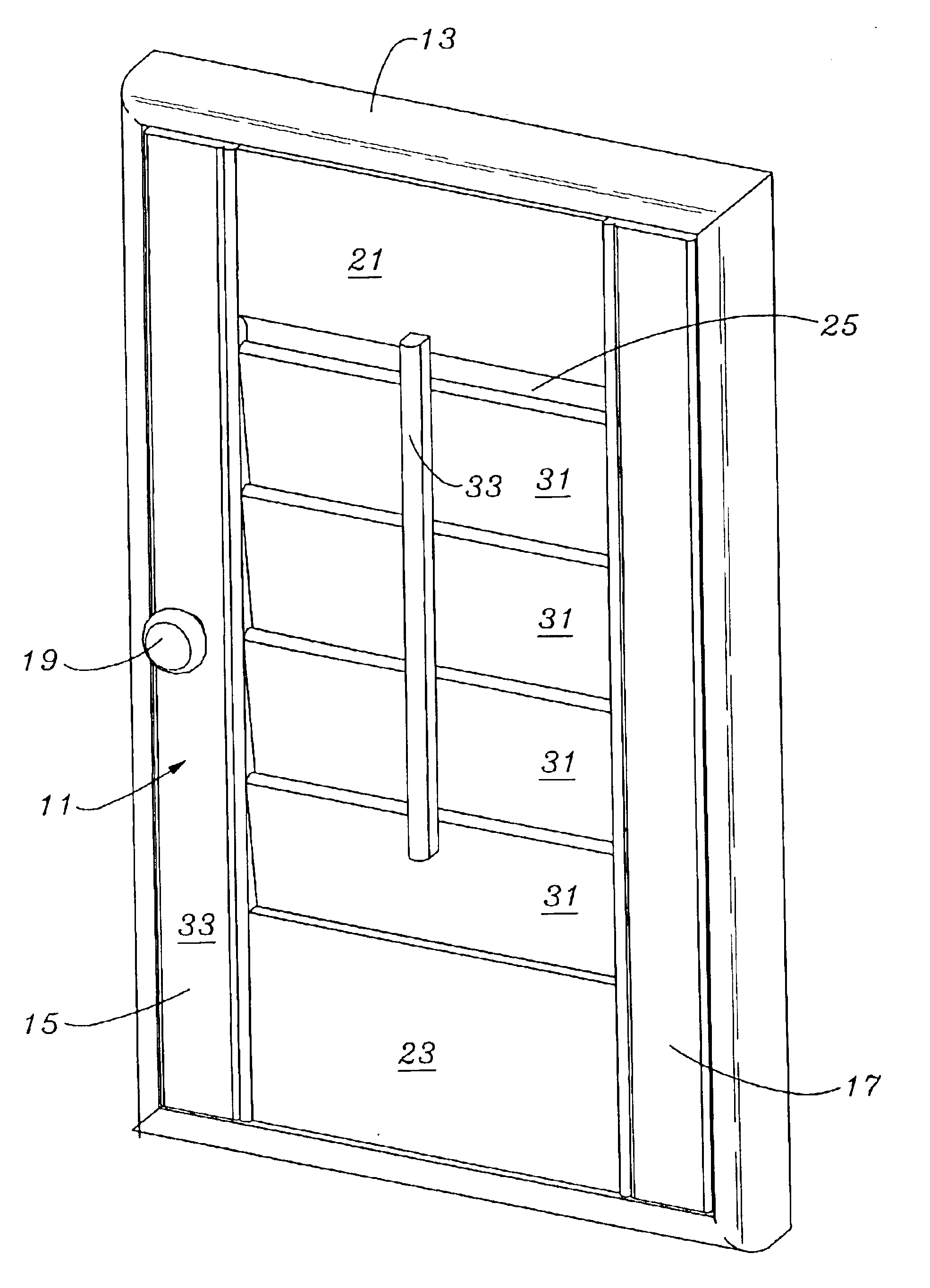
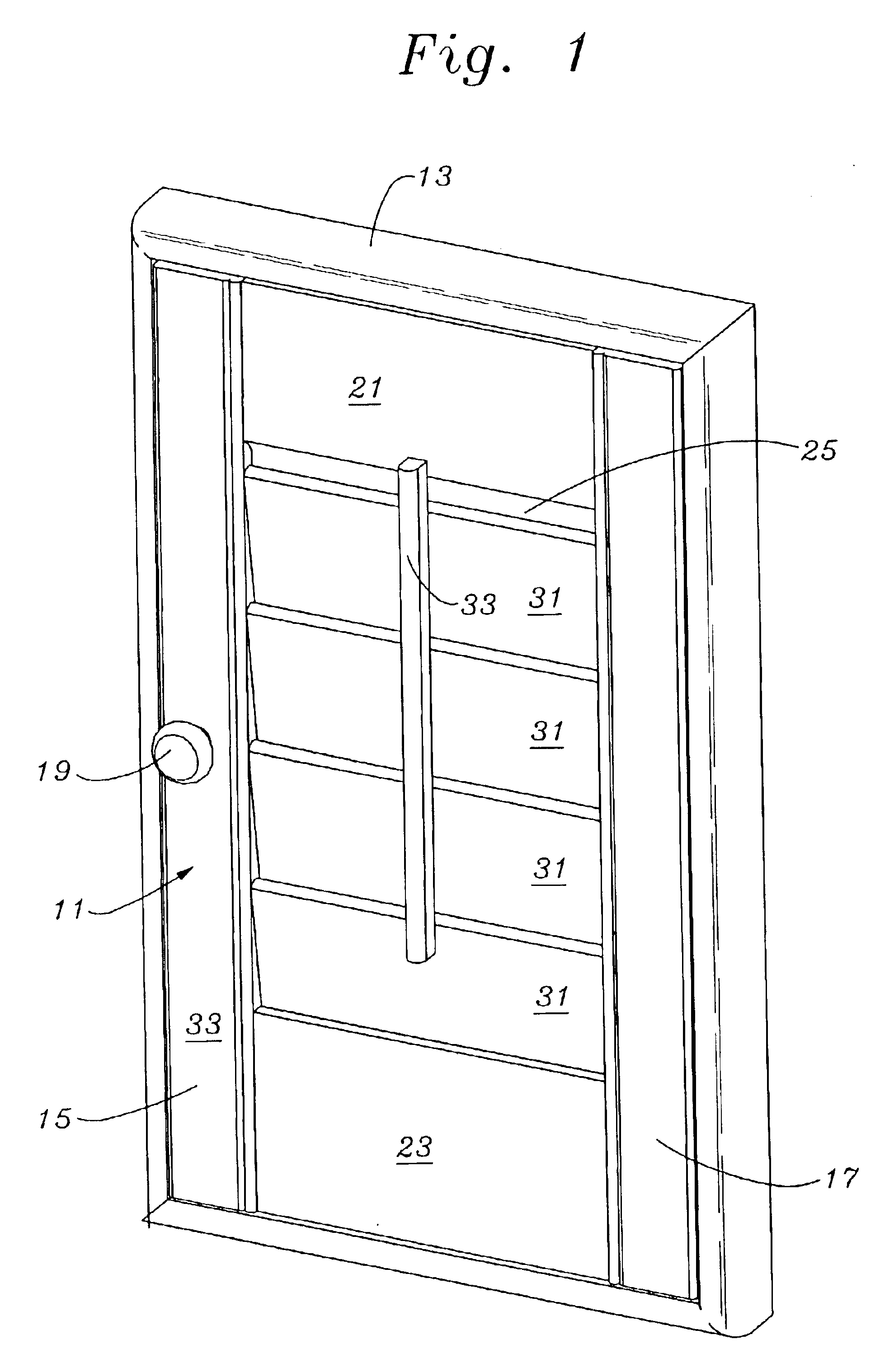
[0020]The description and operation of the shutter system of the invention will be best described with reference to FIG. 1 which illustrates a perspective view of fundamental assembled shutter door 11 within a plain frame 13. The shutter door 11 includes a first vertical member 15 and a second vertical member 17. First vertical member 15 has a knob 19 used to open and close the shutter door 11. The second vertical member 17 typically has a hinge mount so that it can pivot with respect to the frame 13 or with respect to another shutter door 11.

[0021]The shutter door 11 has an upper panel 21 and a lower panel 23 which have side edges which connect to the first and second vertical members 15 and 17. Both the upper and lower panels 21 and 23 have a curved surface 25, which is seen only in the upper panel 21 of FIG. 1. The curved surface 25 of the lower panel 23 faces in the opposite direction.

[0022]Between the upper panel 21 and the lower panel 23, a series of louvers 31 are ultimately ...


PUM


Abstract

A pre-cut, pre-painted shutter door includes a pair of vertical members available in a range of discrete or quantum heights, and having a two level slot along their length for engaging an upper and a lower panel to form the outer portions of a shutter door. Vertical members are preferably pre-tapped with bores to facilitate threaded member access to engagement for attachment to the upper and lower panels. The upper and lower panels have a curved surface to either facilitate direct manual pivoting of the louvers or to provide clearance for an optional common actuator bar. A louver pivot support fits within the two level slot of the vertical members and carries a series of pre-drilled holes for pivotally supporting the louvers. Both the vertical members, panels and louver member supports are of constant cross section to facilitate the use of finger joints and to promote continuous extrusion-type processing. A series of louvers have shafts which extend through pre-drilled holes in the louver pivot supports. Louver shafts may carry gears engaging a gears fittable within a clearance between the louver pivot supports and the more inner level of the two level slot to accommodate a gear rack engaging the gears of the louver shafts to provide simultaneous movement of the louvers with linear translation of the gear rack.

Description

FIELD OF THE INVENTION[0001]The present invention relates to an improvement in providing window covering shutter which are designed to be constructed from materials to give a more finished appearance with more balance in the shutter, including the ability to specify louver and side panel shutter door widths but without the loss of the professional look and without mistake, and expensive scrappage.BACKGROUND OF THE INVENTION[0002]Shutters which fold over window and door openings have been in use and have varying degrees of custom fit. In a typical window installation a poor quality of installation might include spacers which actually move the pivot point for the shutters and shutter sets toward the center of the assembly. This represents the worst solution to make up for a shutter set which is forced to fit a larger window.[0003]In other more sophisticated assemblies the user can add decorative spacers to the shutter doors at either of their vertical sides with the whole shutter pivo...

Claims


Application Information

Patent Timeline
IPC IPC(8): E06B7/096E06B7/02
CPCE06B7/096
Inventor LEE, HAN-SEN
Owner LEE HAN SEN
Why Eureka
Try Eureka