Three-finger mechanical gripper with variable structure

A manipulator claw and configuration technology, applied in manipulators, chucks, manufacturing tools, etc., can solve the problems of large volume and high maintenance cost, and achieve the effect of small overall structure size, low maintenance cost, and reduced requirements.

Active Publication Date: 2015-09-16
HARBIN INST OF TECH
View PDF6 Cites 32 Cited by
  • Summary
  • Abstract
  • Description
  • Claims
  • Application Information

AI Technical Summary

Problems solved by technology

[0008] In order to solve the problems of the existing three-finger robotic grippers, such as large volume, high maintenance cost, and certain limitations in the grasping configuration of the entire gripper, a three-finger robotic gripper with a variable configuration is provided.

Method used


Image

  • Three-finger mechanical gripper with variable structure
  • Three-finger mechanical gripper with variable structure
  • Three-finger mechanical gripper with variable structure

Examples


specific Embodiment approach 1

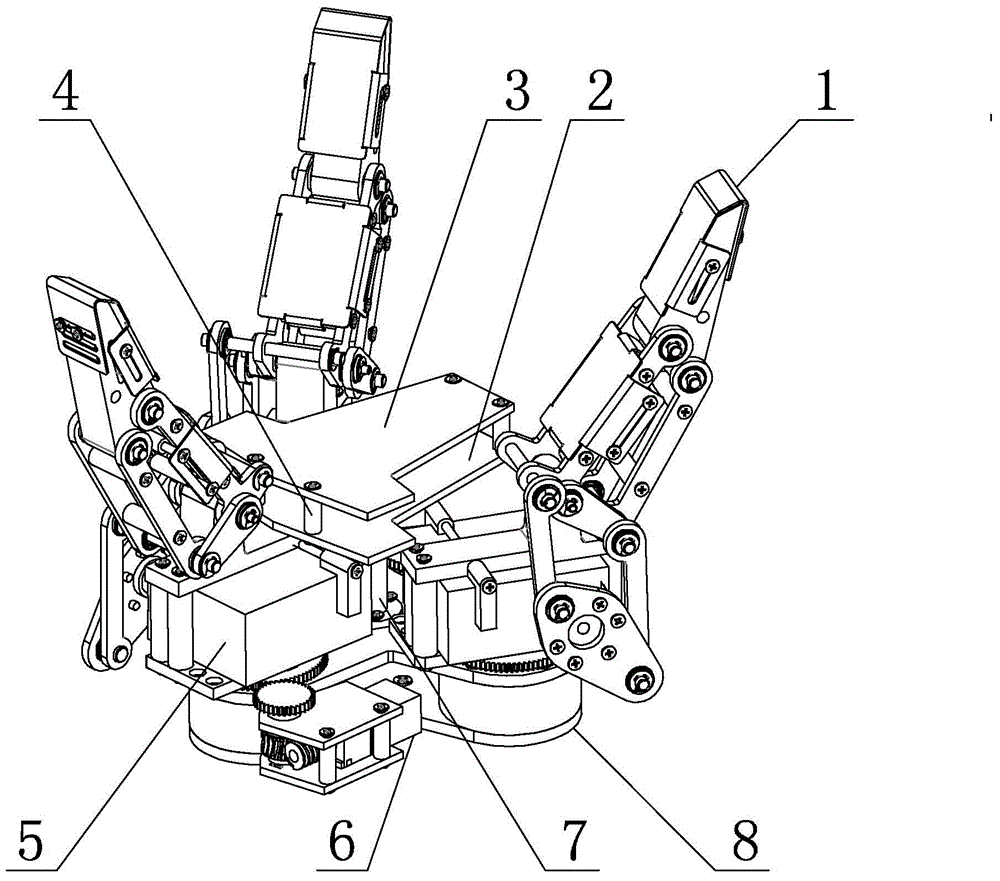
[0017] Specific implementation mode one: as Figure 1~6 As shown, the variable-configuration three-finger mechanical gripper of this embodiment includes a palm, a rotating base 8, a central cylinder 7, three rotating shafts 21, three rotating tables 20, three finger bottom motors 6, and three turbines. 23, three worms 24, three large spur gears 22, three small spur gears 25 and three fingers 1, three fingers 1 are arranged on the rotating base 8, the palm is composed of a flat plate 2 under the palm, a flat plate 3 on the palm and a plurality of Composed of connecting cylinders 4, the palm upper plate 3 is fixed on the upper end surface of the palm lower plate 2 through a plurality of connecting cylinders 4, the palm upper plate 3 is arranged in parallel with the palm lower plate 2, and the lower end of the palm lower plate 2 is fixed by the central cylinder 7. Installed at the center of the upper end surface of the rotating base 8;

[0018] Each finger comprises a first knuc...

specific Embodiment approach 2

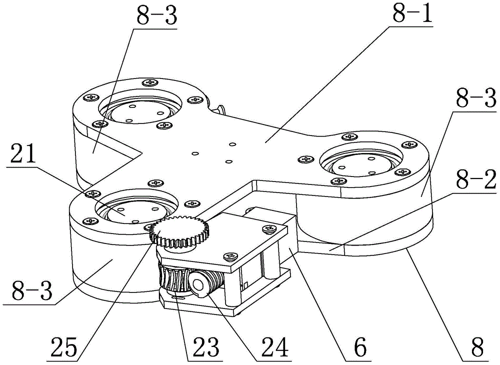
[0021] Specific implementation mode two: as image 3 As shown, the rotating base 8 in this embodiment includes an upper rotating platform 8-1, a lower rotating platform 8-2 and three bearing sleeves 8-3, and the upper rotating platform 8-1 and the lower rotating platform 8-2 are arranged in parallel , three bearing sleeves 8-3 are evenly distributed and fixed between the upper rotating platform 8-1 and the lower rotating platform 8-2, and a rotating shaft 21 is installed in each bearing sleeve 8-3. With such a design, the pointing of each finger can be flexibly adjusted, thereby increasing the diversity of claw configurations. Other components and connections are the same as those in the first embodiment.

specific Embodiment approach 3

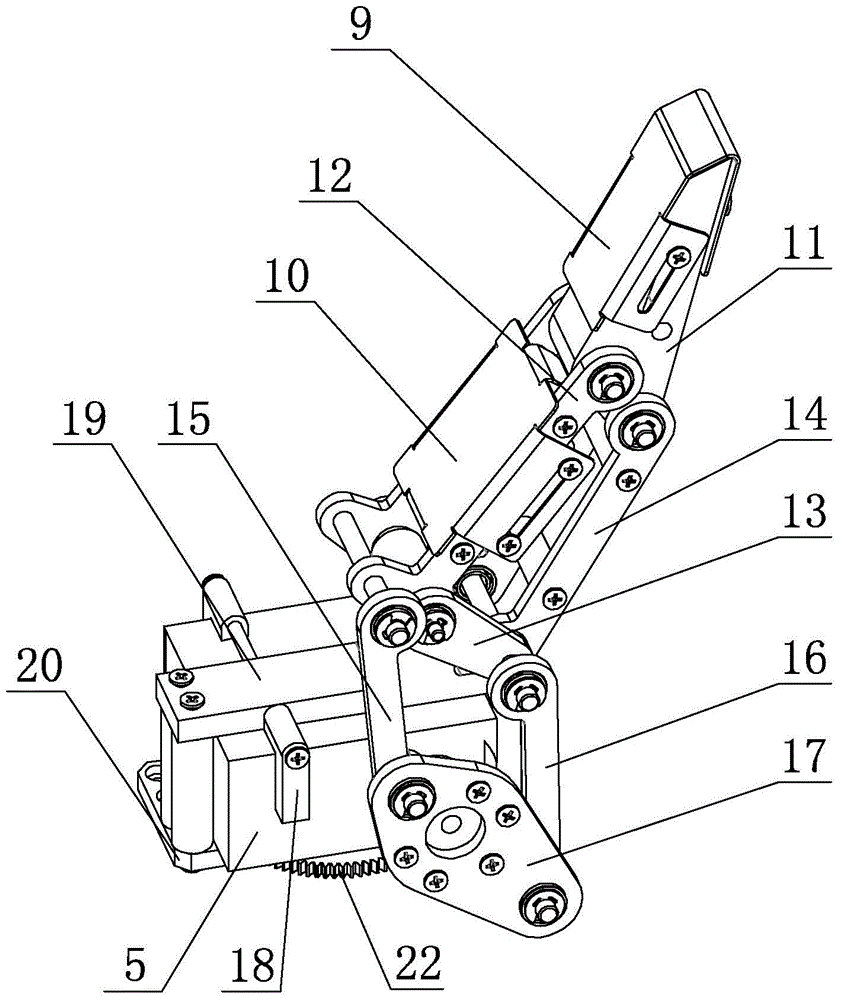
[0022] Specific implementation mode three: as figure 2 As shown, the three-fingered robotic gripper in this embodiment also includes three first knuckle sets 9 , and one first knuckle set 9 is installed on the first knuckle 11 . Such a design can increase the frictional force when the fingers are in contact with the object to ensure the stability of grasping; and can avoid the possible surface wear of the fingers when they are in rigid contact with the object. Other compositions and connections are the same as those in Embodiment 1 or 2.


PUM


Abstract

A three-finger mechanical gripper with a variable structure relates to a three-finger mechanical gripper and solves problems of large size, high maintenance cost and gripping structural limitation of the whole gripper in the present three-finger mechanical gripper. Three rotating shafts are evenly distributed on a rotating pedestal; an output shaft of a motor on the bottom end of each finger is fixedly connected with a corresponding worm rod; each worm rod is engaged with a corresponding worm gear; each small straight gear is engaged with a large straight gear; an output shaft of each finger joint motor is fixedly covered with a coupling connection rod; one end of the coupling connection rod is connected with the tail end of a short side of a second joint via a first driving rod; the other end of the coupling connection rod is connected with one end of a second connection rod and one end of a first connection rod via a second driving rod; the other end of the first connection rod is connected with the second joint; and the tail end of the long side of the second joint and the other end of the second connection rod are both connected with a first joint. The three-finger mechanical gripper with the variable structure can be applied to the technical field of robots.

Description

technical field [0001] The invention relates to a three-finger mechanical gripper, in particular to a variable-configuration three-finger robotic gripper. Background technique [0002] The end effector of the robot is designed by imitating the human hand to have the working ability similar to that of the human hand, so that these mechanical grippers can replace humans to complete the work tasks, which enhances the versatility and flexibility of the robot end effector. In the process of designing the gripper, the structure of the gripper and the gripping configuration of the gripper are important research contents to achieve gripping stability and adaptability. [0003] In the research of the robotic gripper, the design structure of the robot end effector needs to consider how to make the robotic gripper have the flexibility close to the human hand, have a variety of grasping configurations, and be small in size and light in weight. When the number of joints of the robot inc...

Claims


Application Information

Patent Timeline
Patent Type & Authority Applications(China)
IPC IPC(8): B25J15/10B25J15/02
Inventor 张福海付宜利李国志曲家迪
Owner HARBIN INST OF TECH
Why Eureka
Try Eureka