Piezoelectric device, piezoelectric transformer, and method of manufacturing piezoelectric device

a piezoelectric transformer and piezoelectric technology, applied in the direction of piezoelectric/electrostrictive/magnetostrictive devices, electrical transducers, electrical apparatus, etc., can solve the problems of insufficient sound pressure for use as ultrasound transducer devices, the entire beam undergoes bending vibrations, etc., to achieve high efficiency and reliable piezoelectric devices

Active Publication Date: 2018-03-08
MURATA MFG CO LTD
View PDF0 Cites 17 Cited by
  • Summary
  • Abstract
  • Description
  • Claims
  • Application Information

AI Technical Summary

Benefits of technology

[0011]According to the present invention, a highly efficient and reliable piezoelectric device can be provided.

Problems solved by technology

Thus, the entire beam undergoes bending vibrations.
When the bending motion is reduced by such inhibition, sound pressure becomes insufficient for use as an ultrasound transducer device.

Method used


Image

  • Piezoelectric device, piezoelectric transformer, and method of manufacturing piezoelectric device
  • Piezoelectric device, piezoelectric transformer, and method of manufacturing piezoelectric device
  • Piezoelectric device, piezoelectric transformer, and method of manufacturing piezoelectric device

Examples


first embodiment

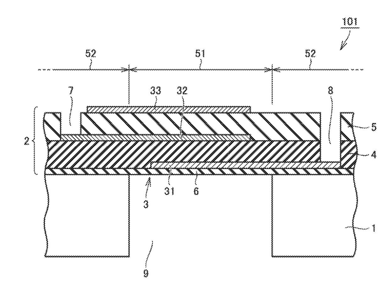
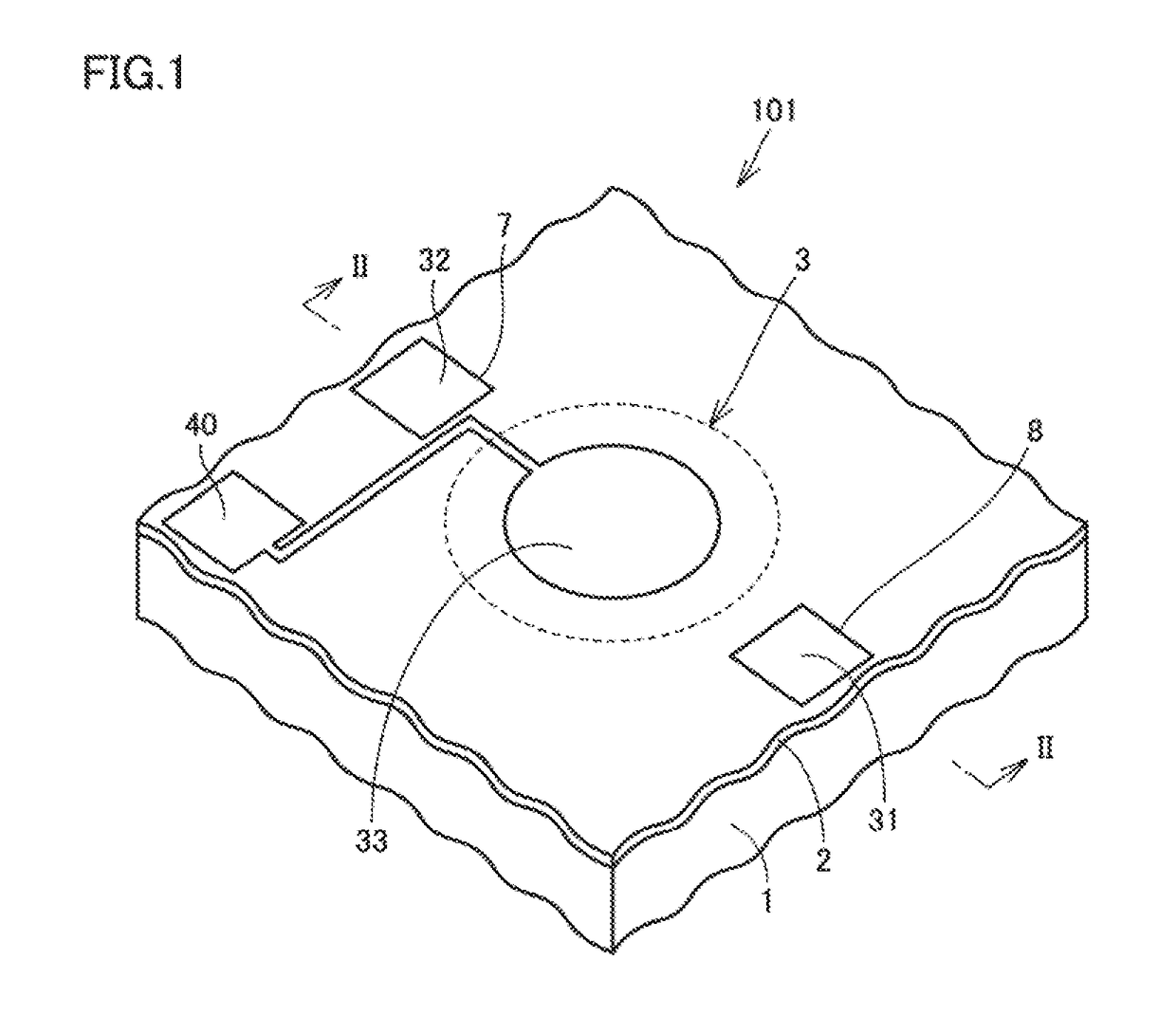
[0078]Referring to FIG. 2, a piezoelectric device in the first embodiment according to the present invention will be hereinafter described. FIG. 1 shows a perspective view of a piezoelectric device 101 in the present embodiment. FIG. 2 shows a cross-sectional view taken along an arrow line in FIG. 1. In FIG. 2, the dimensions in the thickness direction are shown in an exaggerated manner for the sake of explanation.

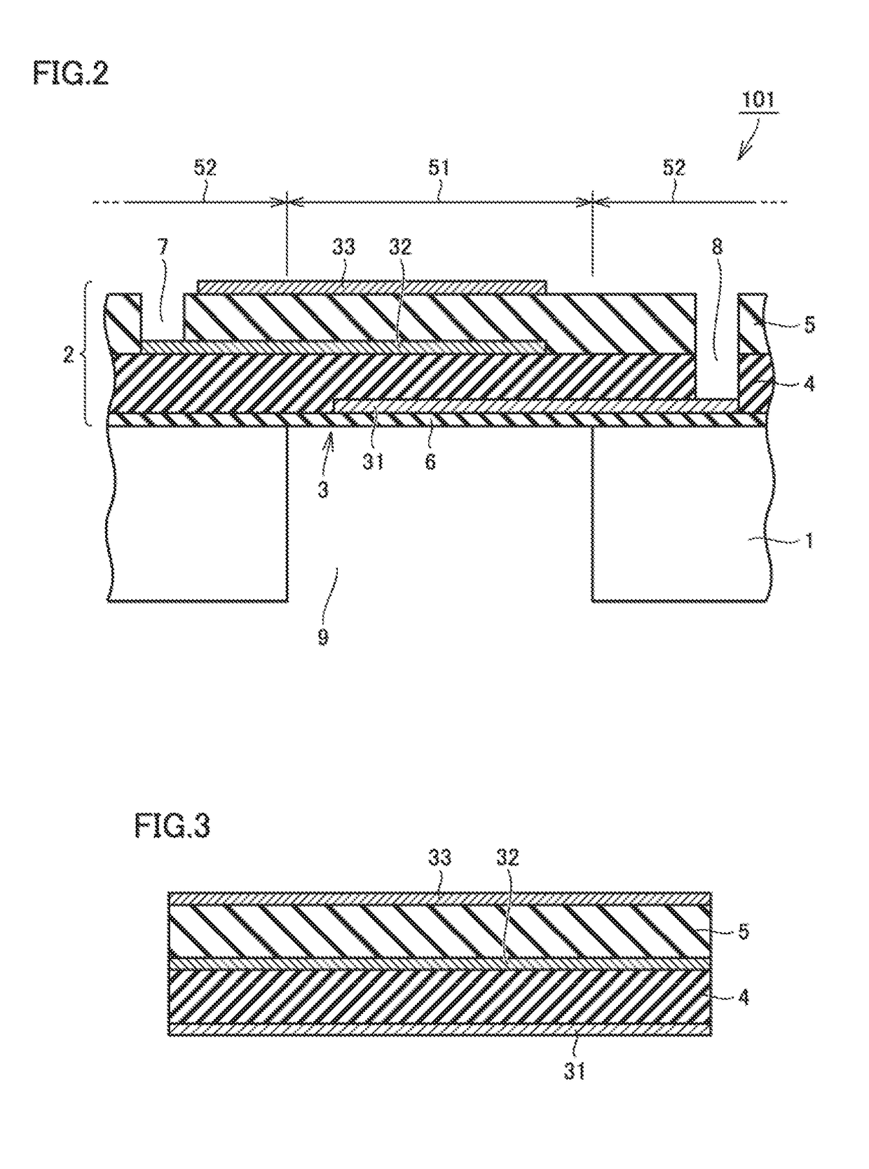
[0079]The piezoelectric device in the present embodiment includes a base member 1 and an upper layer 2 supported by base member 1. Upper layer 2 includes a vibration portion 3 corresponding to a portion 51 not overlapping with base member 1 in upper layer 2. Upper layer 2 includes a lower electrode 31, an intermediate electrode 32 and an upper electrode 33 that are spaced apart from one another in the thickness direction. Upper layer 2 includes a first piezoelectric layer 4 and a second piezoelectric layer 5. First piezoelectric layer 4 is disposed so as to be at least par...

second embodiment

[0123]Referring to FIGS. 10 to 18, a method of manufacturing a piezoelectric device in the second embodiment according to the present invention will be hereinafter described. This manufacturing method can be used for obtaining the piezoelectric device described in the first embodiment.

[0124]The method of manufacturing a piezoelectric device in the present embodiment includes the steps of: preparing a base member having a main surface; forming a lower electrode so as to partially cover the main surface; forming a first piezoelectric layer so as to cover the lower electrode; forming an intermediate electrode so as to partially cover the first piezoelectric layer; forming a second piezoelectric layer so as to cover the intermediate electrode; forming an upper electrode so as to partially cover the second piezoelectric layer; and partially removing the base member to form a vibration portion corresponding to a portion that does not overlap with the base member as a part of an upper laye...

third embodiment

[0134]Referring to FIG. 19, a piezoelectric device in the third embodiment according to the present invention will be hereinafter described. FIG. 19 shows a cross section of a piezoelectric device 102 in the present embodiment. The basic configuration of piezoelectric device 102 in the present embodiment is the same as that of piezoelectric device 101 described in the first embodiment, but is different therefrom in the following points.

[0135]In the present embodiment, an intermediate electrode includes a first intermediate electrode 32a disposed on the side close to lower electrode 31, and a second intermediate electrode 32b disposed on the side close to upper electrode 33. An intermediate protection film 10 is disposed between first intermediate electrode 32a and second intermediate electrode 32b.

[0136]The present embodiment can also achieve the same effects as those in the first embodiment. In the present embodiment, a ground electrode can be divided into two parts. Accordingly, ...


PUM


Abstract

A piezoelectric device that includes a base member having an opening therein and an upper layer supported by the base member. The upper layer includes a vibration portion at a location corresponding to the opening in the base member. The vibration portion includes a lower electrode, an intermediate electrode and an upper electrode that are spaced apart from one another in a thickness direction of the piezoelectric device. The upper layer includes a first piezoelectric layer disposed so as to be at least partially sandwiched between the lower electrode and the intermediate electrode, and a second piezoelectric layer disposed so as to overlap with the first piezoelectric layer and so as to be at least partially sandwiched between the intermediate electrode and the upper electrode. The first piezoelectric layer and the second piezoelectric layer are different in relative permittivity in the thickness direction of the piezoelectric device.

Description

CROSS REFERENCE TO RELATED APPLICATIONS[0001]The present application is a continuation of international application No. PCT / JP2016 / 061547, filed Apr. 8, 2016, which claims priority to Japanese Patent Application No. 2015-093091, filed Apr. 30, 2015, the entire contents of each of which are incorporated herein by reference.FIELD OF THE INVENTION[0002]The present invention relates to a piezoelectric device, a piezoelectric transformer, and a method of manufacturing the piezoelectric device.BACKGROUND OF THE INVENTION[0003]Japanese Patent Laying-Open No. 2014-195495 (PTD 1) discloses an example of a so-called ultrasound transducer device. The device disclosed in PTD 1 includes a base body that includes a substrate and a flexible film (paragraph 0028 in PTD 1). The substrate has a surface on which a flexible film is formed. The substrate is provided with an opening for each element. A part of the flexible film forms a vibration film so as to correspond to the outline of each opening (pa...

Claims


Application Information

Patent Timeline
Patent Type & Authority Applications(United States)
IPC IPC(8): H01L41/09H01L41/107H01L41/314H01L41/187
CPCH01L41/09H01L41/107H01L41/314H01L41/187H04R17/00H04R2201/003H10N30/804H10N30/871H10N30/50H10N30/40H10N30/07H10N30/20H10N30/074H10N30/853
Inventor IKEUCHI, SHINSUKEYAMAMOTO, KANSHOHADA, TAKUOMOCHIDA, YOICHIHORIUCHI, HIDEYA
Owner MURATA MFG CO LTD
Why Eureka
Try Eureka