
System and Articles of Interchangeably Connectable Pre-Wired Segments

Active Publication Date: 2018-03-15
RODGERS MATTHEW
View PDF0 Cites 0 Cited by
  • Summary
  • Abstract
  • Description
  • Claims
  • Application Information

AI Technical Summary

Benefits of technology

The present invention is a building wiring system that allows for easy swapping of various elements without the need for rewiring, tools, or special knowledge. The system includes pre-wired, detachable components that can be easily connected together, making repairs or improvements without the risk of damage or insurance coverage. The system also reduces the packaging footprint for lighting companies, minimizing shipping costs. Overall, the system provides a safer, efficient, and flexible solution for wiring buildings.

Problems solved by technology

While the current NEMA / Edison Screw wiring system reliably provides an electrical connection to power devices, this system cannot be used to provide physical (i.e., load bearing) support.
For example, a typical table lamp cannot be securely mounted using a NEMA connection.
Rather, any force applied to the cord (e.g., if someone trips over the wiring) will immediately unplug the device or, possibly worse, knock the device over.
This is, in part, due to the inability of NEMA / Edison Screw plugs and outlets to bear a load since nearly all elevated electrical devices require structural support in mounting.
Unfortunately, replacing an elevated electrical device follows much of this same routine pattern.
Wiring a new elevated electrical device poses safety risks.
In fact, because of safety and liability concerns, most elevated electrical device manufacturers and building insurance companies require that such wiring be limited to qualified licensed electricians.
Such a requirement dramatically increases remodeling costs.
This poses an additional safety risk as an electrician must work at a height.
Many times, electricians must dangerously work atop a ladder—holding the electrical device in one hand while completing the electrical connection with the other hand.
However, the '746 application is limited to head lighting (i.e., not all elevated electrical devices such as ceiling fans).
Additionally, the '746 application does nothing to promote interoperability with non-elevated electrical devices.
For example, the electrical system discussed in the '746 application would be ill-suited to use in non-elevated electrical devices such as table lamps and floor lamps.

Method used


Image

  • System and Articles of Interchangeably Connectable Pre-Wired Segments
  • System and Articles of Interchangeably Connectable Pre-Wired Segments
  • System and Articles of Interchangeably Connectable Pre-Wired Segments

Examples


Embodiment Construction

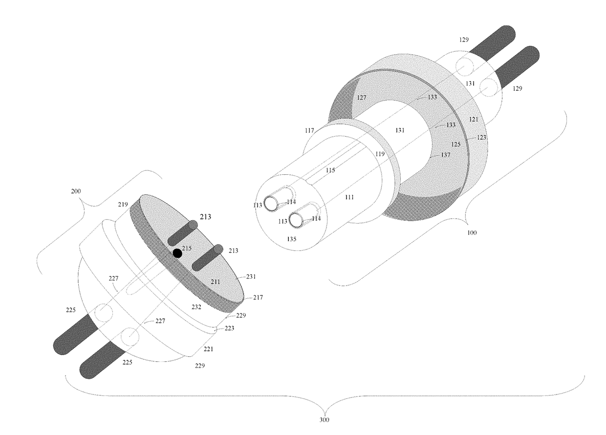
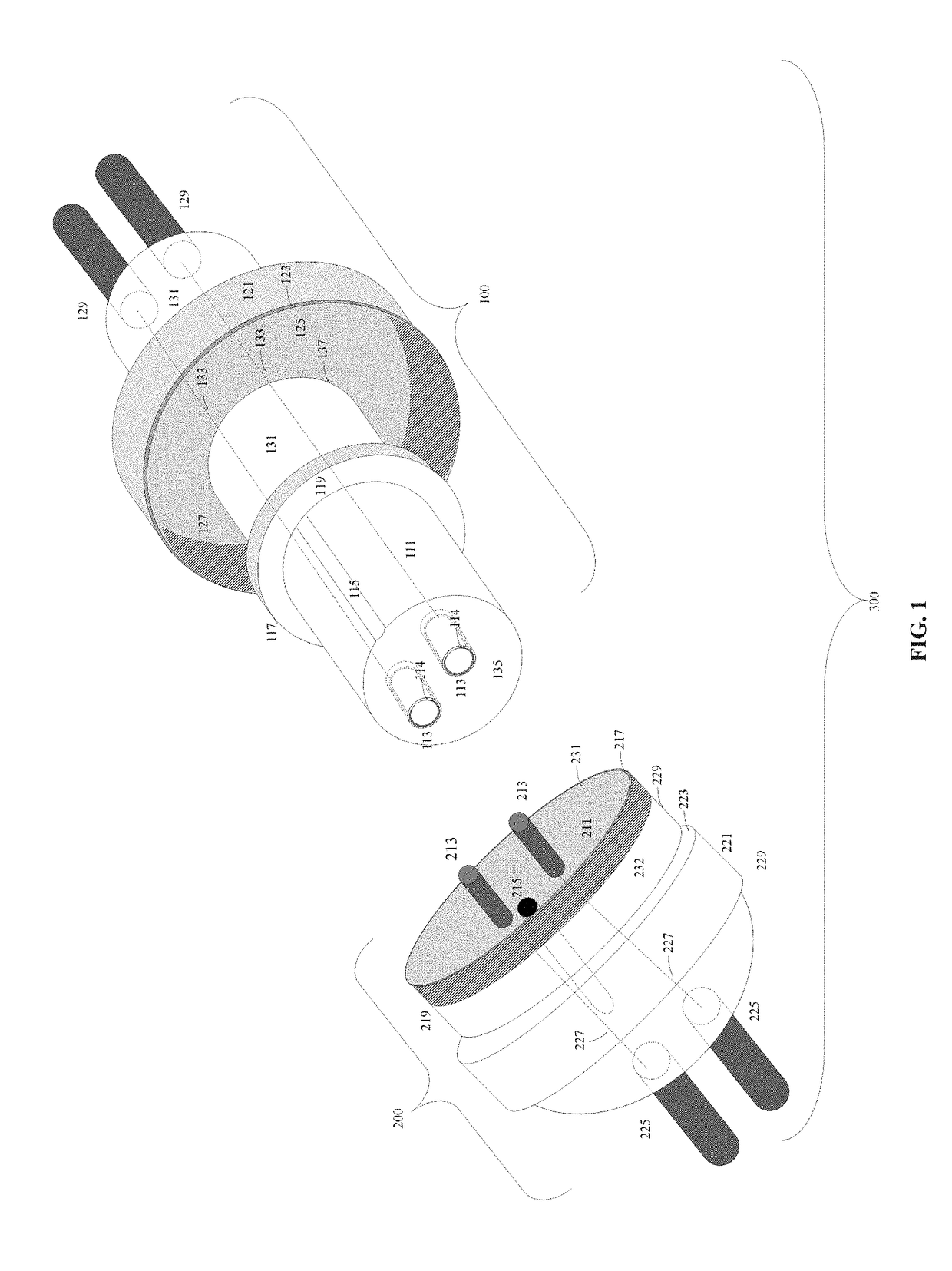
[0083]The present invention discloses a system of interchangeably connectible elements which are prewired and have mating electro-mechanical connectors. FIG. 1 shows one possible embodiment of the mating electro-mechanical connectors, namely, an ungrounded (i.e., two pin) Coupling Assembly 300.

[0084]The Coupling Assembly 300 is comprised of a mating Female Coupling Assembly 100 and a Male Coupling Assembly 200.

[0085]The Female Coupling Assembly 100 comprises a Coupling Shaft 131 attached to a Telescoping Coupling Shaft 111. In the preferred embodiment, the Telescoping Coupling Shaft 111 is formed out of an insulating material. A protruding Female Flange 117 defines the boundary between the Coupling Shaft 131 and the Telescoping Coupling Shaft 111. The Female Flange 117 has a Female Flange Surface 119 such that the plane of the Female Flange Surface 119 is perpendicular to the plane defined by the Telescoping Coupling Shaft 111. A Coupling Groove 115 extends along the cylindrical sur...


PUM


Abstract

Prewired, interchangeably connectible elements with mating electro-mechanical connectors for constructing a multitude of electrical apparatuses by forming load-bearing, electrical connections between the constituent elements thereof and a method of using such elements therefor.

Description

CROSS-REFERENCE TO RELATED APPLICATION[0001]This application claims the benefit of U.S. Provisional Application No. 62 / 354,217, filed on Jun. 24, 2016.BACKGROUND OF THE INVENTION[0002]Since the widespread introduction of the Edison incandescent light, structural electrical wiring has changed very little. Frustratingly, wall mounted electrical devices and ceiling mounted electrical devices typically follow widely divergent plug and receptacle standards.[0003]In the United States, most appliances are wired with NEMA 1 (two-prong plugs, i.e., with no safety ground) or NEMA 5 (three-prong plugs, i.e., with a safety ground) plugs. Wall receptacles are typically wired with NEMA 5-15R outlets. Typical light bulbs still follow the Edison Screw socket standard first introduced in the early 1900s.[0004]While the current NEMA / Edison Screw wiring system reliably provides an electrical connection to power devices, this system cannot be used to provide physical (i.e., load bearing) support. For e...

Claims


Application Information

Patent Timeline
IPC IPC(8): H01R33/08H01R33/06H01R13/703
CPCH01R33/0827H01R13/703H01R33/06H01R13/622H01R33/94F21V21/35
Inventor RODGERS, MATTHEW
Owner RODGERS MATTHEW
Learn More