Techniques for generating dynamic effects animations

a dynamic effects and animation technology, applied in the field of computer processing, can solve the problems of unacceptably time-consuming and tedious key framing, unaccessible to many users, and difficulty in achieving dynamic effects animations via key framing, so as to reduce time and expertise, time and expertise

Active Publication Date: 2018-03-22
AUTODESK INC
View PDF3 Cites 8 Cited by
  • Summary
  • Abstract
  • Description
  • Claims
  • Application Information

AI Technical Summary

Benefits of technology

[0008]One advantage of the disclosed techniques is that the techniques provide artistic control while reducing the time and expertise required to generate dynamic effects animations. In particular, because the graphical objects are updated automatically based on the flow particles, the time and expertise required to produce a realistic dynamic effects animation is dramatically less than the time and expertise that would be required to perform key framing.

Problems solved by technology

However, because key framing is a manual process, key framing may be unacceptably time consuming and tedious.
Further, producing a realistic dynamic effects animation via key framing requires both artistic expertise and knowledge of dynamic effects.
Therefore, key framing is not accessible to many users.
One drawback to using physical simulation tools, however, is that animators are oftentimes unable to understand and control how the physical simulation tools cause the appearance of the 2D graphical objects to evolve.
Consequently, dynamic effects animations generated via physical simulation tools do not always meet the artistic goals of the animator.
For example, an animator may be unable to configure the physical simulation tools to generate a dynamic effects animation that depicts wind-blown hair in a desired fashion.

Method used


Image

  • Techniques for generating dynamic effects animations
  • Techniques for generating dynamic effects animations
  • Techniques for generating dynamic effects animations

Examples


Embodiment Construction

[0015]In the following description, numerous specific details are set forth to provide a more thorough understanding of the present invention. However, it will be apparent to one of skill in the art that the present invention may be practiced without one or more of these specific details.

System Overview

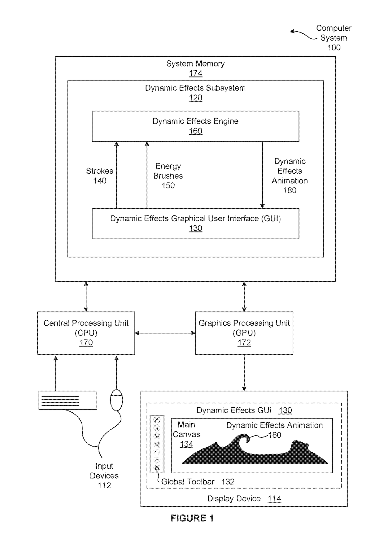
[0016]FIG. 1 is a conceptual illustration of a computer system 100 configured to implement one or more aspects of the present invention. As shown, the computer system 100 includes, without limitation, a central processing unit (CPU) 170, input devices 112, a graphics processing unit (GPU) 172, a display device 114, and a system memory 174. For explanatory purposes, multiple instances of like objects are denoted with reference numbers identifying the object and parenthetical numbers identifying the instance where needed.

[0017]The CPU 170 receives user input from the input devices 112, such as a keyboard or a mouse. In operation, the CPU 170 is the master processor of the computer syste...


PUM


Abstract

In one embodiment, a dynamic effects subsytem automatically generates a dynamic effects animation. A graphical user interface enables an animator to sketch applied energies that influence graphical objects. Each applied energy includes flow particles that are associated with velocity fields. Over time, a dynamic effects engine moves the flow particles and the associated velocity fields along a overall direction associated with the applied energy. To generate each frame included in the dynamic effects animation, the dynamic effect engine computes samples of the graphical objects, computes the influences of the velocity fields on the samples, and updates the positions of the samples based on the influences of the velocity fields. Notably, the applied energies and the flow particles enable the animator to effectively and interactively control the automated animation operations of the dynamic effects engine. Consequently, the resulting dynamic effects animation meets artistic, performance, and physical accuracy goals.

Description

CROSS-REFERENCE TO RELATED APPLICATIONS[0001]This application claims the priority benefit of the U.S. Provisional patent application having Ser. No. 62 / 398,445 (Attorney Docket Number AUTO / 1394USL) and filed on Sep. 22, 2016. The subject matter of this related application is hereby incorporated herein by reference.BACKGROUND OF THE INVENTIONField of the Invention[0002]Embodiments of the present invention relate generally to computer processing and, more specifically, to techniques for generating dynamic effects animations.Description of the Related Art[0003]As part of generating an illusion of motion or change for two-dimensional (2D) graphical objects, an animator often generates a “dynamic effects animation.” Such an animation is a sequence of frames that visually conveys passive and secondary visual effects that are driven by underling forces that change over time. For example, a dynamic effects animation for wind-blown hair could be a sequence of frames that depicts distortions ...

Claims


Application Information

Patent Timeline
Patent Type & Authority Applications(United States)
IPC IPC(8): G06T13/80G06T7/246G06T7/73
CPCG06T13/80G06T7/248G06T2207/10016G06T2200/24G06T7/74G06T2210/56
Inventor XING, JUNKAZI, RUBAIAT HABIBGROSSMAN, TOVIWEI, LI-YISTAM, JOSFITZMAURICE, GEORGE
Owner AUTODESK INC
Why Eureka
Try Eureka