Fan-out package structure having stacked carrier substrates and method for forming the same

Active Publication Date: 2018-03-22
MEDIATEK INC
View PDF4 Cites 4 Cited by
  • Summary
  • Abstract
  • Description
  • Claims
  • Application Information

AI Technical Summary

Problems solved by technology

As a result, the manufacturing cost of the package substrate is greatly increased, while the yield of the package substrate is reduced.
These cause reductions

Method used


Image

  • Fan-out package structure having stacked carrier substrates and method for forming the same
  • Fan-out package structure having stacked carrier substrates and method for forming the same
  • Fan-out package structure having stacked carrier substrates and method for forming the same

Examples


Embodiment Construction

[0033]The following description is of the best-contemplated mode of carrying out the invention. This description is made for the purpose of illustrating the general principles of the invention and should not be taken in a limiting sense. The scope of the invention is determined by reference to the appended claims.

[0034]The present invention will be described with respect to particular embodiments and with reference to certain drawings, but the invention is not limited thereto and is only limited by the claims. The drawings described are only schematic and are non-limiting. In the drawings, the size of some of the elements may be exaggerated for illustrative purposes and not drawn to scale. The dimensions and the relative dimensions do not correspond to actual dimensions in the practice of the invention.

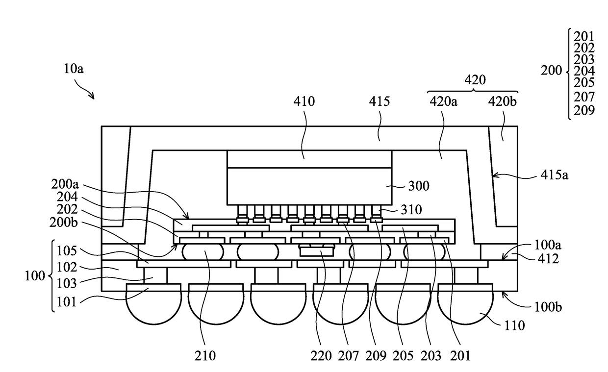
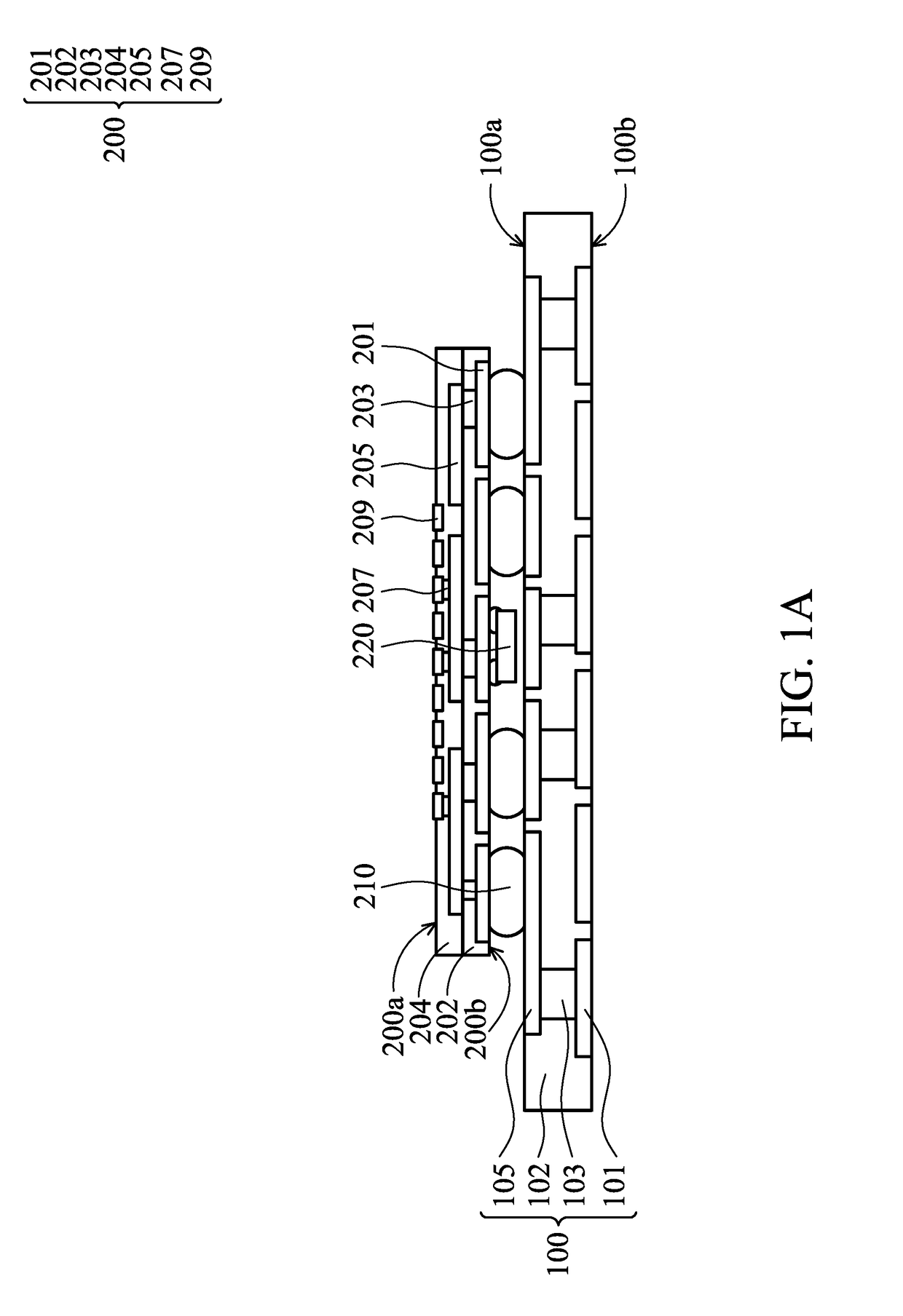
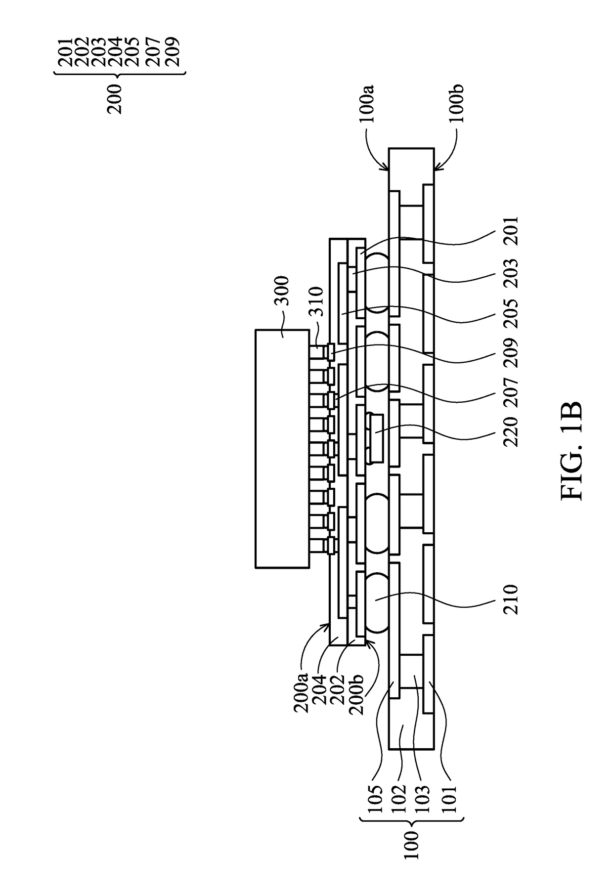
[0035]FIG. 1E is a cross-sectional view of a semiconductor package structure 10a in accordance with some embodiments of the disclosure. In some embodiments, the semiconductor package ...


PUM


Abstract

A semiconductor package structure is provided. The semiconductor package structure includes a first carrier substrate having a first surface and an opposing second surface. A second carrier substrate is stacked on the first carrier substrate and has a first surface and an opposing second surface that faces the first surface of the first carrier substrate. A semiconductor die is mounted on the first surface of the second carrier substrate. A heat spreader is disposed on the first surface of the first carrier substrate to cover and surround the second carrier substrate and the semiconductor die. A method for forming the semiconductor package structure is also provided.

Description

CROSS REFERENCE TO RELATED APPLICATIONS[0001]This application claims the benefit of U.S. Provisional Application No. 62 / 396,906 filed on Sep. 20, 2016, the entirety of which is incorporated by reference herein.BACKGROUND OF THE INVENTIONField of the Invention[0002]The present invention relates to a semiconductor package structure, and in particular to a highly cost-effective fan-out package structure and a method for forming the same.Description of the Related Art[0003]In the semiconductor packaging industry, there is a demand for reducing the manufacturing cost of semiconductor packages. To accomplish this, various package structure designs have been developed. One of the package structure designs currently in use is the flip-chip package structure. The adoption of a flip chip package structure in many applications is driven by performance needs and the ability to achieve a smaller die with a flip chip design.[0004]In a flip-chip package structure, a semiconductor die (also referre...

Claims


Application Information

Patent Timeline
IPC IPC(8): H01L23/498H01L23/42H01L23/64H01L23/31H01L21/48
CPCH01L23/49833H01L23/42H01L23/642H01L23/3135H01L21/4857H01L21/563H01L23/3121H01L23/49811H01L23/3675H01L23/4334H01L24/13H01L24/16H01L24/32H01L24/73H01L24/81H01L24/83H01L24/92H01L2224/131H01L2224/16227H01L2224/32225H01L2224/32245H01L2224/73204H01L2224/73253H01L2224/81815H01L2224/83191H01L2224/92125H01L2224/92225H01L2924/1431H01L2924/1432H01L2924/15311H01L2924/16251H01L2924/164H01L2924/18161H01L2924/19041H01L2924/19105H01L2924/19106H01L2224/1308H01L23/49816H01L2924/014H01L2924/00014H01L2224/16225H01L2924/00H01L25/0657H01L23/3107
Inventor SYU, SHIH-YIJIN, CHIA-YUCHOU, CHE-YAHSU, WEN-SUNGCHEN, NAN-CHENG
Owner MEDIATEK INC
Why Eureka
Try Eureka