Fluid material ejecting apparatus

a technology of fluid ejecting and ejecting parts, which is applied in the direction of process efficiency improvement, additive manufacturing, manufacturing tools, etc., can solve the problems of difficult stably ejecting fluid materials, sliding surfaces are prone to wear, and the fluid material is difficult to stably eject. , to achieve the effect of high vickers hardness and stably ejecting

Inactive Publication Date: 2018-03-29
SEIKO EPSON CORP
View PDF4 Cites 3 Cited by
  • Summary
  • Abstract
  • Description
  • Claims
  • Application Information

AI Technical Summary

Benefits of technology

[0005]An advantage of some aspects of the invention is to allow a fluid material containing particles having a high Vickers hardness, such as metal particles and ceramic particles, to be stably ejected over a long period of time.

Problems solved by technology

When the fluid material contains particles that constitute the 3D modeled object, it is sometimes difficult to stably eject the fluid material.
In particular, when the particles are metal particles or ceramic particles, which have a high Vickers hardness, the piston may wear in the liquid chamber owing to continuous use of the fluid material ejecting apparatus, making it difficult to stably eject the fluid material over a long period of time.
Although with such a configuration the sliding surfaces are prone to wear because of the particles contained in the fluid material, employing a material higher in Vickers hardness than the particles contained in the fluid material to form the sliding surfaces prevents the wear and allows the fluid material to be stably ejected over a long period of time.

Method used


Image

  • Fluid material ejecting apparatus
  • Fluid material ejecting apparatus
  • Fluid material ejecting apparatus

Examples


first embodiment

[0026]First, a fluid material ejecting apparatus (manufacturing apparatus of a 3D modeled object) according to a first embodiment of the invention will be described.

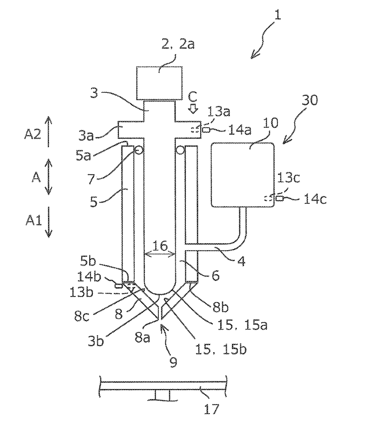
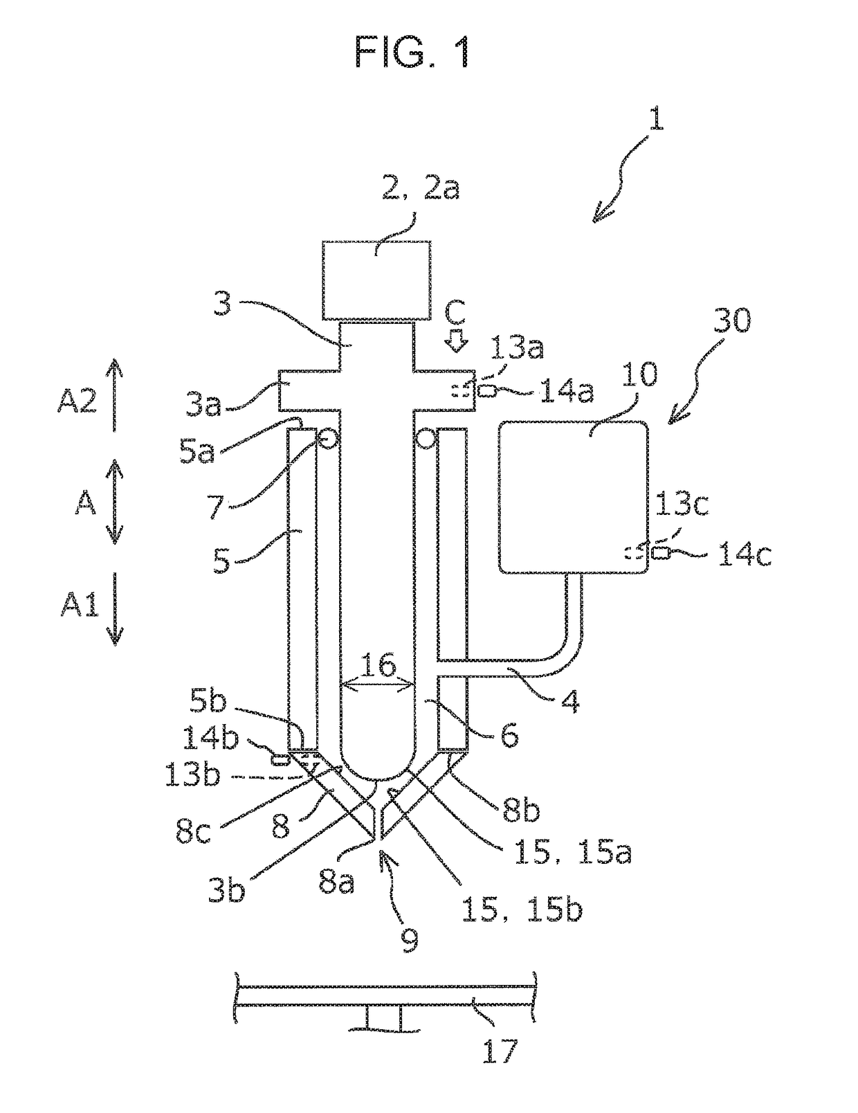
[0027]FIG. 1 is a schematic side view of a fluid material ejecting apparatus 1 according to this embodiment.

[0028]Although the fluid material ejecting apparatus 1 is exemplified by the manufacturing apparatus of the 3D modeled object in this embodiment, the fluid material ejecting apparatus 1 may be a different apparatus provided that the apparatus is configured to eject a fluid material M (see FIG. 3 to FIG. 5). For example, the fluid material ejecting apparatus 1 may be an ink jet recording apparatus that records an image on a sheet-shaped recording medium.

[0029]The fluid material ejecting apparatus 1 according to this embodiment includes a cylindrical main portion 5 connected via a tube 4 to a cartridge 10a in which the fluid material M for forming the 3D modeled object is stored, a piston 3 inserted in the main porti...

second embodiment

[0076]Hereunder, the fluid material ejecting apparatus 1 according to a second embodiment will be described in detail with reference to the drawings.

[0077]FIG. 6 is a schematic side view of the fluid material ejecting apparatus 1 according to the second embodiment, viewed in the same direction as FIG. 1 illustrating the fluid material ejecting apparatus 1 according to the first embodiment.

[0078]The fluid material ejecting apparatus 1 according to the second embodiment has the same configuration as that of the fluid material ejecting apparatus 1 according to the first embodiment, except for the structure of the driver 2, and the same components as those of the fluid material ejecting apparatus 1 according to the first embodiment are given the same numeral.

[0079]The driver 2 according to the first embodiment includes the piezoelectric element 2a, to deform the piezoelectric element 2a in the direction A1 so as to press the piston 3 in the direction A1, by applying a voltage to the pie...


PUM

PropertyMeasurementUnit
thicknessaaaaaaaaaa
Vickers hardnessaaaaaaaaaa
hardnessaaaaaaaaaa

Abstract

A fluid material ejecting apparatus includes a material chamber to which a fluid material containing at least one of metal particles and ceramic particles is supplied, a valve seat constituting a part of the material chamber and including an ejection port, a piston movable in the material chamber in directions toward and away from the ejection port, and a driver of the piston. The driver is configured to cause the piston to contact the valve seat from a position away from the valve seat and move in the direction toward the ejection port so as to slide along the valve seat, to thereby eject the fluid material through the ejection port. Sliding surfaces of the piston and the valve seat via which the piston and the valve seat contact each other have a higher Vickers hardness than the particles contained in the fluid material.

Description

BACKGROUND1. Technical Field[0001]The present invention relates to a fluid material ejecting apparatus.2. Related Art[0002]Fluid material ejecting apparatuses are known that are configured to supply a fluid material to a material chamber and drive (move) a piston in the material chamber, to thereby eject the fluid material through an ejection port of the material chamber.[0003]For example, WO2008 / 108097 discloses a liquid droplet ejecting apparatus (fluid material ejecting apparatus) configured to supply a liquid to a liquid chamber and drive a piston in the liquid chamber, to thereby eject the liquid through an ejection port of the liquid chamber.[0004]Recently, users of the fluid material ejecting apparatus have come to require the apparatus to eject various types of fluid materials. For example, the fluid material ejecting apparatus may be utilized to form a three-dimensional (hereinafter, 3D) modeled object, in which case a metal or ceramic material may be employed as the materi...

Claims


Application Information

Patent Timeline
Patent Type & Authority Applications(United States)
IPC IPC(8): B22F3/00B28B13/00B33Y30/00B28B1/00
CPCB33Y30/00B28B13/00B22F3/008B28B1/001B22F3/003C04B2235/6026Y02P10/25B22F12/222B22F12/53B22F12/90B22F10/22B33Y70/10
Inventor ISHIDA, MASAYAMIYASHITA, TAKESHIOKAMOTO, EIJITSUNOYA, AKIHIKOSHIMA, NAOKO
Owner SEIKO EPSON CORP
Why Eureka
Try Eureka