External anchoring harpoon for aircraft

a technology for aircraft and anchoring harpoons, which is applied in aircraft components, ground installations, and landing gear, etc., can solve the problems of significant loss of fuel working volume, large risk of damage to the tank, and complex and burdensome solutions, so as to reduce mechanical stresses generated on the components of the component, the effect of small vertical siz

Active Publication Date: 2018-03-29
EUROCOPTER
View PDF0 Cites 4 Cited by
  • Summary
  • Abstract
  • Description
  • Claims
  • Application Information

AI Technical Summary

Benefits of technology

[0023]An object of the present invention is to be unaffected by the above-mentioned limitations and to propose an external anchoring harpoon that is of small vertical size, and as a result that does not intrude into the structure of the aircraft. Furthermore, the external anchoring harpoon of the invention provides a wide range of m

Problems solved by technology

As a result, structural modifications of the aircraft are needed, leading in particular to a significant loss of the working volume of fuel.
Nevertheless, since a telescopic actuator is made up o

Method used


Image

  • External anchoring harpoon for aircraft
  • External anchoring harpoon for aircraft
  • External anchoring harpoon for aircraft

Examples


first embodiment

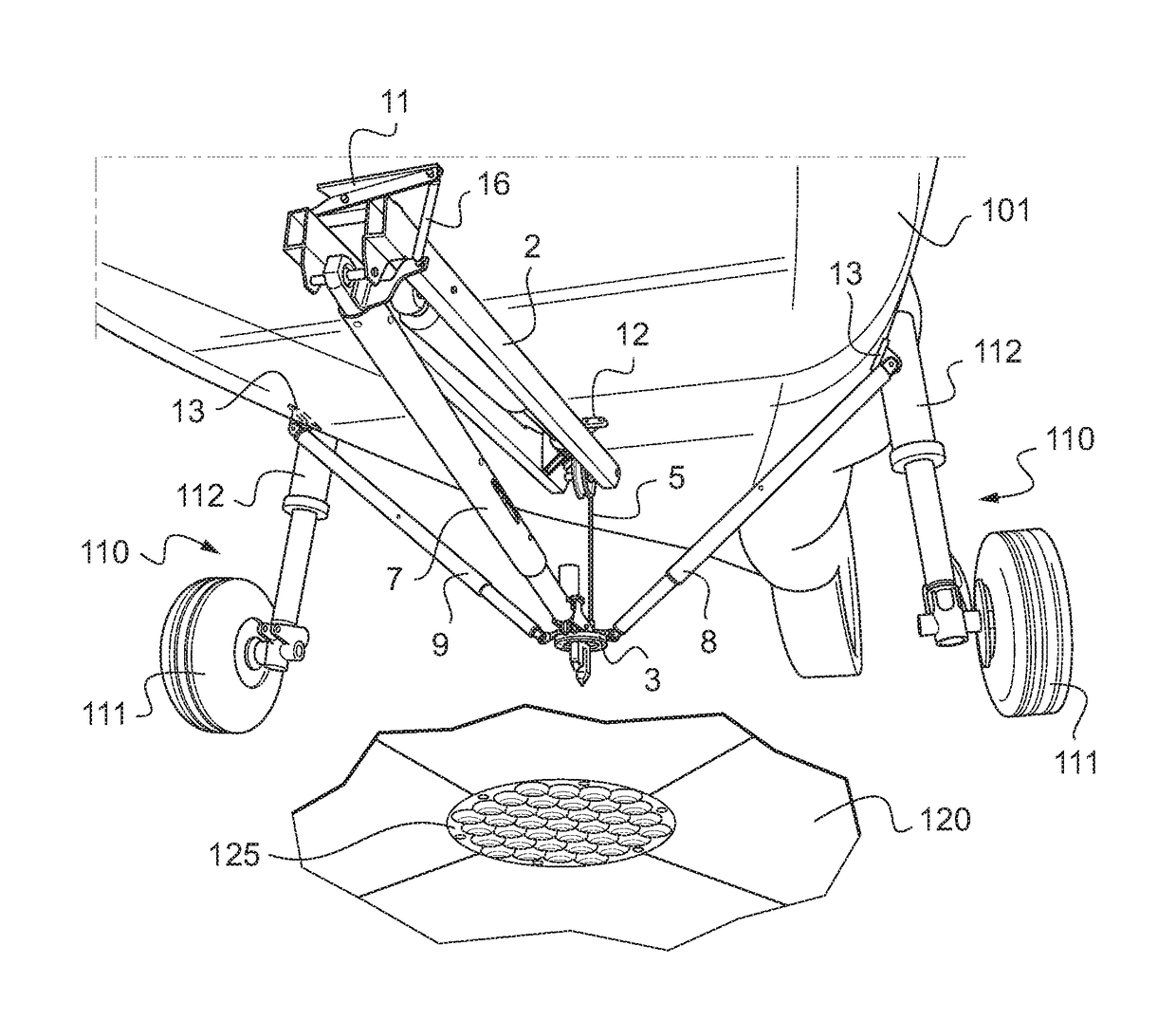
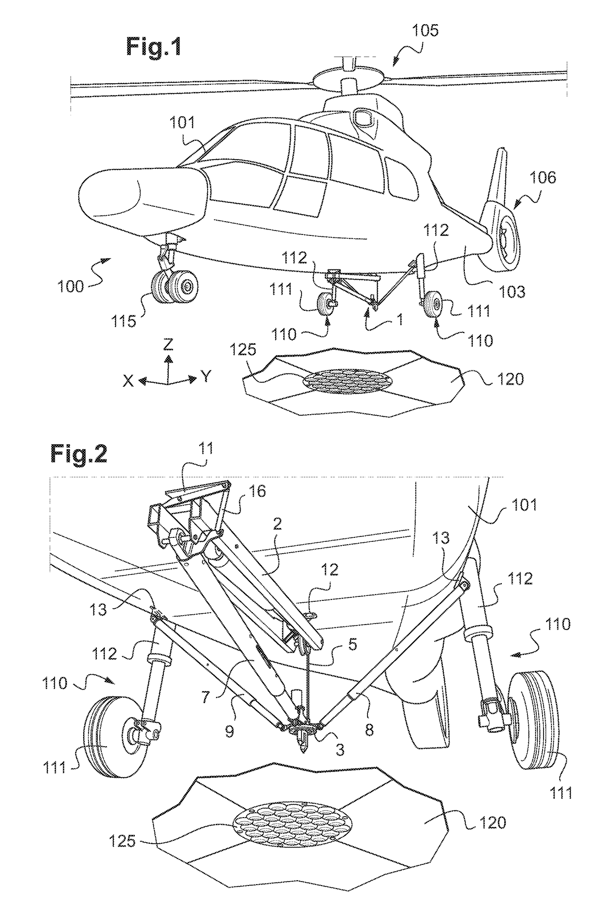
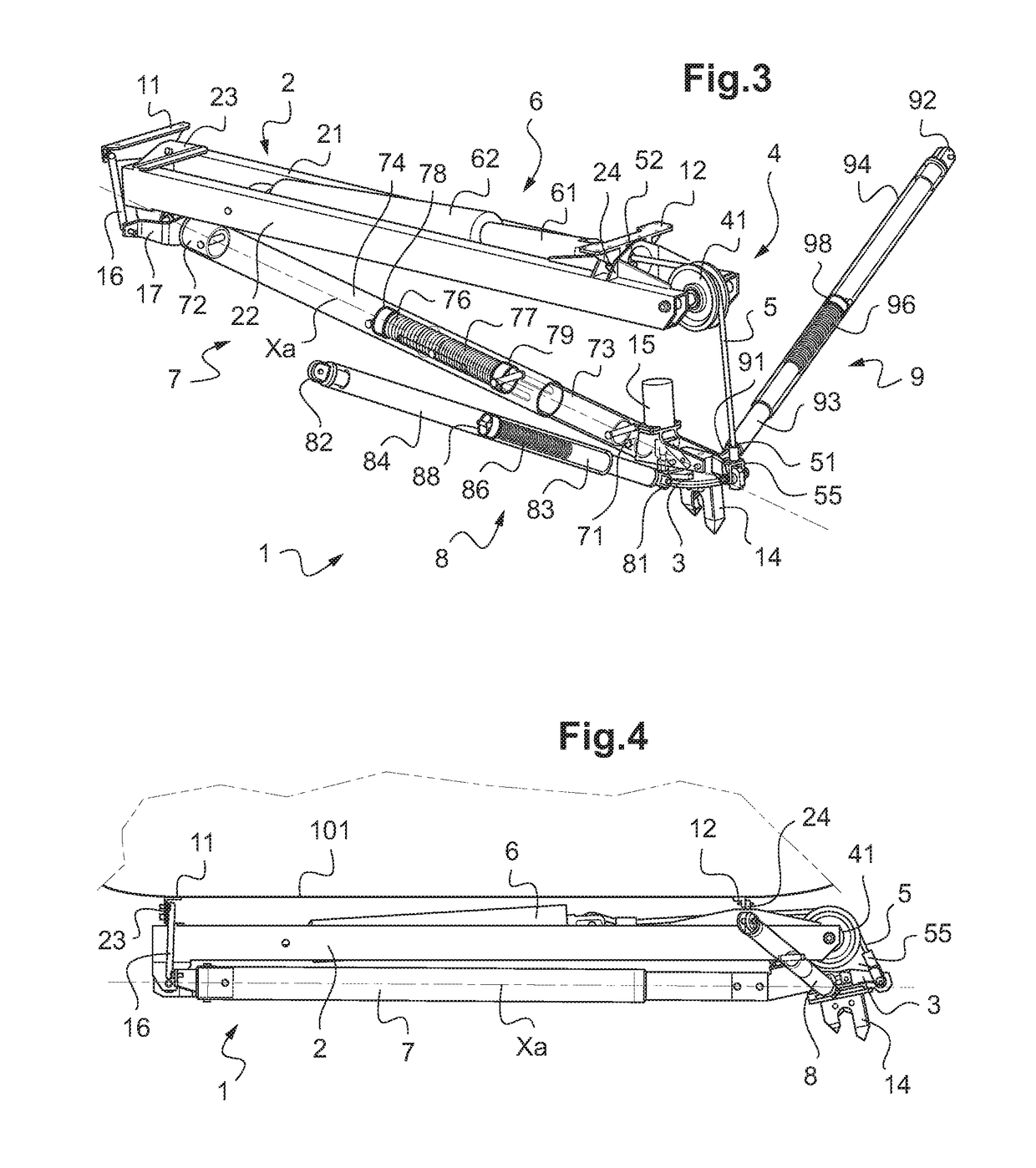
[0114]FIGS. 2 to 4 show the external anchoring harpoon 1 for which the deployment device 4 comprises two secondary struts 8 and 9 arranged on either side of the harpoon head 3, each being provided with single second resilient means 86, 96.

[0115]FIG. 2 shows in greater detail how the external anchoring harpoon 1 is installed on the bottom face of the fuselage 101. The two secondary struts 8, 9 are connected via their sixth ends 82, 92 by respective supports 13 at strong points of the structure of the aircraft 100. The two secondary struts 8, 9 are situated in a plane that also contains the harpoon head 3 and the axis of the wheels 111, this plane being substantially parallel to the transverse elevation directions Y and Z. Furthermore, since the two secondary struts 8 and 9 are situated on either side of the harpoon head 3, the two second resilient means 86, 96 behave like two opposing resilient means.

[0116]The projections of the main strut 7 and of each secondary strut 8, 9 onto a ho...

second embodiment

[0118]FIGS. 5 and 6 show the external anchoring harpoon 1, in which the deployment device 4 has only one secondary strut 8 together with a tensioning scissors linkage 30. This secondary strut 8 has two second resilient means 86, 87 constituting opposing resilient means, and it is preferably connected via its sixth end 82 and a support 13 to a strong point of the structure. The secondary strut 8 lies in a plane that is substantially parallel to the transverse and elevation directions Y and Z and that contains the harpoon head 3 and the axis of the wheels 111.

[0119]The projections of the main strut 7 and of the secondary strut 8, 9 onto a horizontal plane form between them an angle of about 90°.

[0120]The tensioning scissors linkage 30 is formed by a pantograph 31 with two traction springs 32, 32′ constituting third resilient means. The pantograph 31 has two sets of links 33, 33′, 34, 34′ and it is made as two symmetrical portions connected together by four hinge pins 35, 36, 37, and 3...


PUM


Abstract

An external anchoring harpoon for an aircraft in order to anchor the aircraft on an anchor grid of a platform, the external anchoring harpoon comprises a frame connected to the aircraft, a harpoon head, and a deployment device for deploying the harpoon head. The deployment device comprises a cable, a movement device for moving the cable connected to the frame, the cable being connected to the harpoon head and to the movement device. The deployment device also comprises a main telescopic strut and two secondary telescopic struts so as to enable the harpoon head to be centered under the aircraft and so as to enable the harpoon head to be anchored to the anchor grid.

Description

CROSS-REFERENCE TO RELATED APPLICATIONS[0001]This application claims priority to French patent application No. FR 16 01387 filed on Sep. 23, 2016, the disclosure of which is incorporated in its entirety by reference herein.BACKGROUND OF THE INVENTION(1) Field of the Invention[0002]The present invention lies in the field of means for holding an aircraft on a platform, e.g. situated on a ship or indeed a building.[0003]The present invention relates to an external anchoring harpoon for aircraft, such as a rotary wing aircraft or indeed a drone, for example. The present invention also relates to an aircraft having such an external anchoring harpoon.(2) Description of Related Art[0004]An anchoring harpoon for an aircraft has two functions. Firstly it serves to provide assistance and safety while landing the aircraft on a ship, and secondly it serves to create an anchor point between the aircraft and the platform of the ship so as to hold the aircraft in a substantially stationary positio...

Claims


Application Information

Patent Timeline
IPC IPC(8): B64F1/12
CPCB64F1/125B64C25/32B64C25/68B64C2025/325
Inventor BISTUER, OLIVIERRENAUD, JEAN PAULGARCIN, PATRICEPRUD'HOMME LACROIX, PIERRE
Owner EUROCOPTER
Why Eureka
Try Eureka