System for driving and guiding of a trailing edge control surface

a technology of control surface and driving system, which is applied in the direction of mechanical equipment, transportation and packaging, aircraft, etc., can solve the problems of relatively complex installation of different kinematics on two supports of a single trailing edge flap, and achieve the effect of simplifying installation and preventing constraint forces

Active Publication Date: 2018-04-05
AIRBUS OPERATIONS GMBH
View PDF0 Cites 3 Cited by
  • Summary
  • Abstract
  • Description
  • Claims
  • Application Information

AI Technical Summary

Benefits of technology

[0031]In an advantageous embodiment, one of the second guide device and the connecting means is adapted for moving along a linear axis relative to the other one of the second guide device and the connecting means. The linear axis may particularly be parallel to the leading edge of the control surface, such that the width between the inboard section of the control surface and the attachment position of the second guide device is variable. This allows to prevent constraint forces.
[0032]One of the second guide device and the connecting means may comprise an elongate component and the other one of the second guide device and the connecting means comprises a component having an opening for receiving the elongated component. This simplifies the installation and leads to a sufficiently determined support of the control surface.

Problems solved by technology

Providing different kinematics on two supports of a single trailing edge flap may be relatively complex.

Method used


Image

  • System for driving and guiding of a trailing edge control surface
  • System for driving and guiding of a trailing edge control surface
  • System for driving and guiding of a trailing edge control surface

Examples


Embodiment Construction

[0042]The following detailed description is merely illustrative in nature and is not intended to limit the embodiments of the subject matter or the application and uses of such embodiments. As used herein, the word “exemplary” means “serving as an example, instance, or illustration.” Any implementation described herein as exemplary is not necessarily to be construed as preferred or advantageous over other implementations. Furthermore, there is no intention to be bound by any expressed or implied theory presented in the preceding technical field, background, brief summary or the following detailed description.

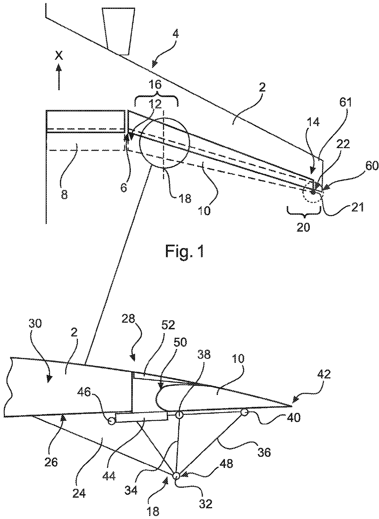
[0043]FIG. 1 shows a wing 2 of an aircraft having a leading edge 4 and a trailing edge region 6. At an inboard region of the wing 2, an inboard trailing edge control surface 8 is movably supported on the wing 2. It may be moved along an x-direction, which is the longitudinal axis of the aircraft.

[0044]At a further outboard region, an outboard trailing edge control surface 10 is ...


PUM


Abstract

A system for driving and guiding a trailing edge control surface arranged on a wing of an aircraft includes a first guide device attachable to the wing and coupled with an inboard section of the control surface for guiding the inboard section along a trajectory relative to the trailing edge region of the wing between a retracted position and an extended position, a second guide device attachable to the wing and holding a connecting means of an outboard section of the control surface, and a drive device attachable to the wing and the control surface for moving the control surface. The trajectory is a spatial path at least along one dimension, wherein a distance between the inboard section of the control surface and a fixed part of the wing changes during a motion of the inboard section on the trajectory.

Description

CROSS-REFERENCE TO PRIORITY APPLICATION[0001]This application claims the benefit of, and priority to, European patent application number 16191862.8, filed Sep. 30, 2016. The entire content of this priority application is incorporated by reference herein.TECHNICAL FIELD[0002]Embodiments of the subject matter described herein relate generally to a system for driving and guiding of a trailing edge control surface arranged on a trailing edge region of a wing of an aircraft, a method for moving a trailing edge control surface relative to a trailing edge region of a wing of an aircraft, and an aircraft having a wing and at least one system for driving and guiding of a trailing edge control surface arranged on a trailing edge region of the wing.BACKGROUND[0003]Wings of civil aircraft are often equipped with a plurality of different control surfaces, which are movably supported on the wing. During flight, the control surfaces are exposed to an airflow and, depending on their orientation to ...

Claims


Application Information

Patent Timeline
Patent Type & Authority Applications(United States)
IPC IPC(8): B64C13/30B64C9/16
CPCB64C13/30B64C9/16B64C9/12B64C13/28F16C2326/43F16C23/045B64C9/02
Inventor LORENZ, FLORIAN
Owner AIRBUS OPERATIONS GMBH
Why Eureka
Try Eureka