A temperature self-adaptive tower beam along-bridge direction constraint method and system

A constraint system and self-adaptive technology, applied to bridges, cable-stayed bridges, bridge forms, etc., can solve the problems of low tension, long elastic tie rods, and increase the cost of the main tower, so as to reduce the size of the foundation and reduce the bending moment , cost-saving effect

Active Publication Date: 2019-05-03
CHINA MAJOR BRIDGE ENERGINEERING
View PDF3 Cites 0 Cited by
  • Summary
  • Abstract
  • Description
  • Claims
  • Application Information

AI Technical Summary

Problems solved by technology

However, this scheme constrains the deformation of the main beam under temperature load, increases the control bending moment of the main tower, and increases the cost of the main tower
And the elastic tie rod is generally longer, the tension force is lower, the sag effect is obvious, and the stiffness loss of the elastic cable is obvious
[0006] None of the existing restraint schemes can simultaneously improve the stress of the main girder under the action of temperature and wind load, and the main tower under the action of live load, and cannot simultaneously reduce the beam end displacement of the main girder

Method used


Image

  • A temperature self-adaptive tower beam along-bridge direction constraint method and system
  • A temperature self-adaptive tower beam along-bridge direction constraint method and system
  • A temperature self-adaptive tower beam along-bridge direction constraint method and system

Examples


Embodiment Construction

[0041] The present invention will be described in further detail below in conjunction with the accompanying drawings and embodiments.

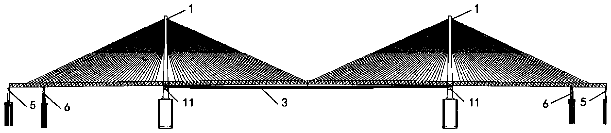
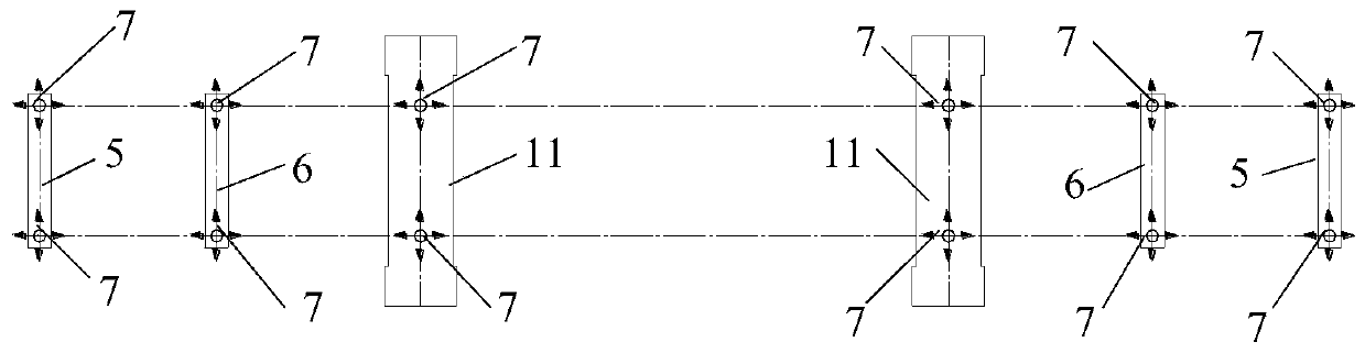
[0042] An embodiment of the present invention provides a method for constraining a temperature-adaptive tower girder along the direction of the bridge. This method is used in conjunction with a temperature-adaptive tower girder along-bridge restraint system. figure 1 It is an overall schematic diagram of the temperature-adaptive tower girder along the bridge direction restraint system in the embodiment of the present invention, figure 2 It is a top view structure schematic diagram of the temperature adaptive tower girder along the bridge direction restraint system in the example of the present invention. Such as figure 1 with figure 2 As shown, this method is applied to the cable-stayed bridge of this system. During the construction of the bridge, or after the bridge is completed, the longitudinal constraints on the main girder can be add...


PUM


Abstract

The invention discloses a temperature self-adaptive tower beam along-bridge constraint method. The method comprises the steps that firstly, the sectional area A of pull rods is determined according tofinite element calculation, then two pull rods are arranged on the two sides of a main beam between two main towers, one end of each pull rod is connected with a lower cross beam of the correspondingmain tower, and the other end of each pull rod is connected with the center point of a lower chord on the main beam. On the other hand, the invention also discloses a temperature self-adaptive towerbeam along-bridge constraint system which comprises two main towers, and each main tower is provided with a lower cross beam. And the main beam penetrates through the two main towers and is arranged on the lower cross beam, and lower chord members are arranged on the two sides of the main beam. Two pull rods are arranged on the two sides of the main beam between the two main towers, one end of each pull rod is connected with the lower cross beam of the corresponding main tower, and the other end of each pull rod is connected with the center point of the lower chord rod on the main beam. According to the invention, the stress condition of the main beam under the action of temperature and wind load and the action of live load can be effectively improved at the same time, and the beam end displacement of the main beam is reduced at the same time.

Description

technical field [0001] The invention relates to the field of restraint systems of long-span bridge structures, in particular to a temperature-adaptive tower girder restraint method and system along the direction of the bridge. Background technique [0002] At present, with the advancement of science and technology, bridge spans are constantly being refreshed. Long-span bridges have large spans and heavy loads. Under the action of wind load, temperature load and live load, the main girder will produce a large beam end displacement, and the main tower will produce a large bending moment. It is necessary to adopt appropriate technical solutions to improve the beam end displacement and the main tower bending moment. According to the traditional practice, damping constraint schemes, limit constraint schemes, and elastic cable constraint schemes are generally used between towers and beams. The above constraint scheme has the following disadvantages: [0003] (1) Damping constra...

Claims


Application Information

Patent Timeline
Patent Type & Authority Applications(China)
IPC IPC(8): G06F17/50E01D11/04
Inventor 秦顺全高宗余苑仁安徐伟庄勇傅战工陆勤丰胡骏郑清刚周子明
Owner CHINA MAJOR BRIDGE ENERGINEERING
Why Eureka
Try Eureka