Device and method for controlling speed of rolling door

Active Publication Date: 2018-04-05
HSIEH CHUNG HSIEN
View PDF0 Cites 0 Cited by
  • Summary
  • Abstract
  • Description
  • Claims
  • Application Information

AI Technical Summary

Benefits of technology

The present invention is about a device and method for controlling the speed of a rolling door to improve its operation speed. The control module can set a position before the door panel opens or closes, at which speed the door panel is designed to start decelerating. The control module also has a memory unit to store acceleration and deceleration values. When the door panel's rolling speed exceeds the range of safety values, the control module stops the door panel to prevent damage or danger. The method can speed up or slow down the operation of the door panel based on its real-time rolling speed, ensuring safe and stable operation. This invention can save energy and reduce waiting time for opening or closing the door panel.

Problems solved by technology

However, in cases where the opening or closing stroke of the rolling door is relatively long, the waiting time will be lenghty, and both time and energy would be wasted.
However, such control mode is not flexible enough to cope with different requirements and changes, and is only applicable to a rolling door that is to be fully opened or closed.
Therefore, the size, type or material of the door panel may be different, which will result in weight difference.
However, door panels of different weights will have different operation loads.
If the rolling speed of the rolling door is controlled by only the absolute position, the door operator may be damaged due to overload during acceleration, or may result in risk as the operation speed of the door operator may be too fast due to underweight of the load.
However, even though it is possible to calculate the real-time absolute position of the rolling door, there are still difficulties in the application of the concept to control the operation speed of the rolling door system.

Method used


Image

  • Device and method for controlling speed of rolling door
  • Device and method for controlling speed of rolling door
  • Device and method for controlling speed of rolling door

Examples


Embodiment Construction

[0023]Before describing a rolling door speed control device and the control method thereof according to the invention in detail in the embodiment, it is noted particularly that, like elements are designated by the same numeral in the description below. Further, drawings of the invention are only illustrative and are not necessarily drawn to scale, and not all details are shown in the drawings.

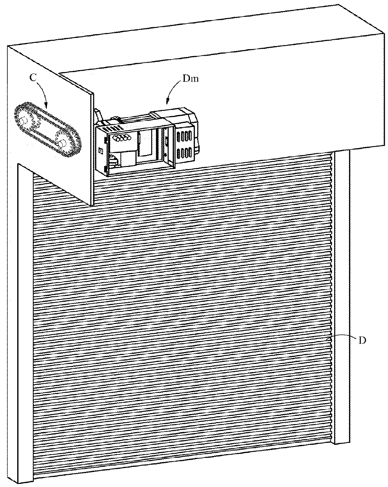
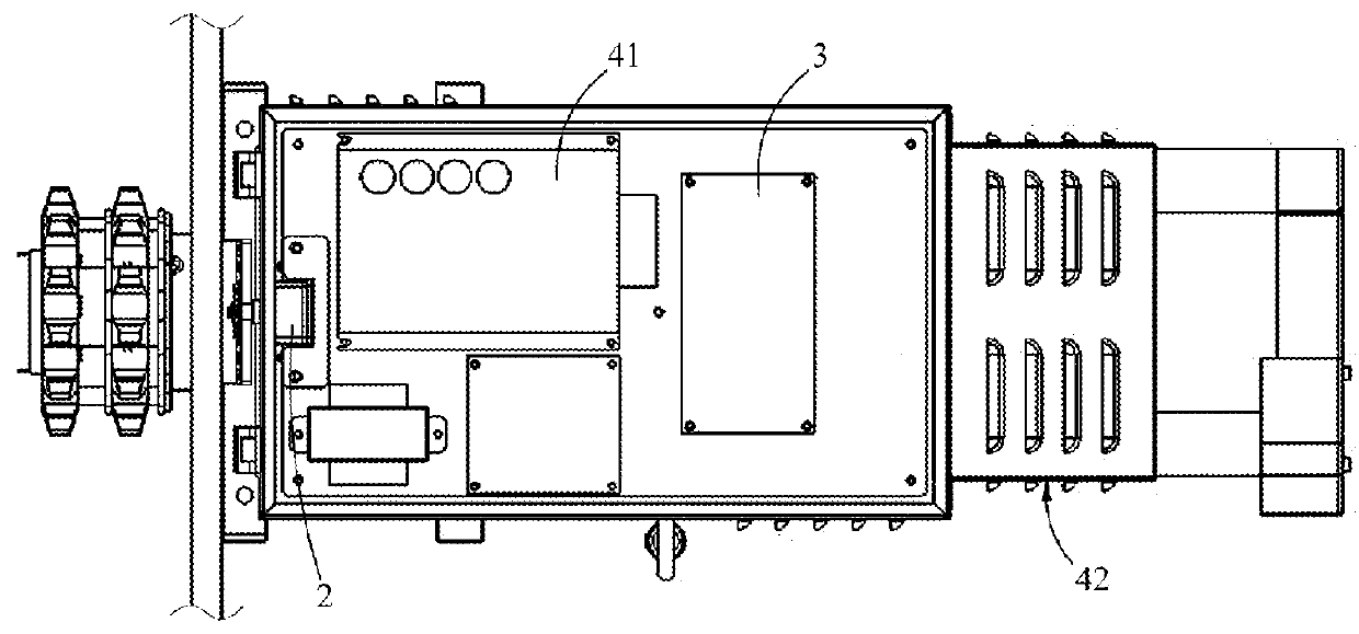
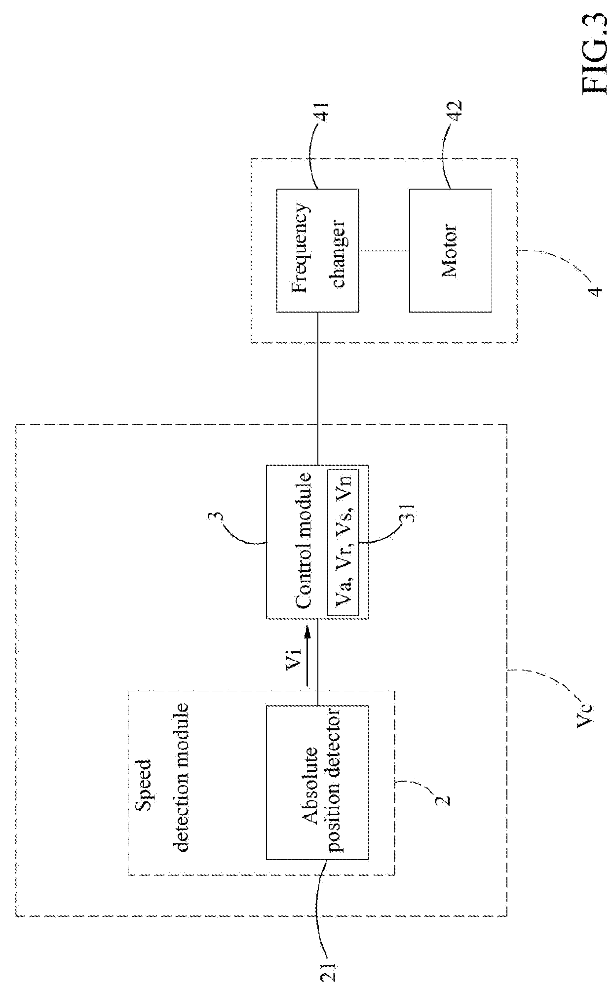
[0024]Refer to FIGS. 1, 2 and 3, in which FIG. 1 is an overall schematic view of a preferred embodiment according to the invention, FIG. 2 is a schematic view showing a driving module and a rolling door speed control device of a preferred embodiment according to the invention, and FIG. 3 is a system architecture diagram of a preferred embodiment according to the invention. As shown in FIG. 1, a door operator Dm is connected to a door panel D through a transmission chain C, to drive and control opening or closing of the door panel D.

[0025]Further, as shown in FIGS. 2 and 3, the door operator Dm ...


PUM


Abstract

A device and method for controlling the speed of a rolling door is disclosed. The door panel is controlled to accelerate or decelerate by means of the real-time rolling speed of the door panel, such that speed control is applicable to door panels of different specifications. When the real-time rolling speed of a door panel reaches a predetermined acceleration value, a control module actuates the driving module to speed up opening or closing of the door panel. When the real-time rolling speed of the door panel reaches a predetermined deceleration value, the control module controls the driving module to speed down opening or closing of the door panel; when the real-time rolling speed of the door panel is in between the acceleration value and the deceleration value, the control module actuates the driving module to maintain the opening or closing speed of the rolling door at current value.

Description

FIELD OF THE INVENTION[0001]The present invention relates to a device and method for controlling the speed of a rolling door, particularly to a rolling door speed control device and method for controlling the speed of opening or closing the rolling door.BACKGROUND OF THE INVENTION[0002]Nowadays, the average door operator is set up to open or close the rolling door at a constant speed. That is, a rolling door is operated at a constant speed. However, in cases where the opening or closing stroke of the rolling door is relatively long, the waiting time will be lenghty, and both time and energy would be wasted. Therefore, a rolling door system with a variable operation speed is urgently needed by the industries and the public. There are existing art that make use of absolute positions to control the rolling speed of a rolling door, in which the rolling speed is accelerated or decelerated as a predetermined position is reached. However, such control mode is not flexible enough to cope wi...

Claims


Application Information

Patent Timeline
IPC IPC(8): E06B9/68E06B9/11
CPCE06B9/68E06B2009/6845E06B2009/6809
Inventor HSIEH, CHUNG-HSIEN
Owner HSIEH CHUNG HSIEN
Why Eureka
Try Eureka