Valve with proportional electromagnetic actuator

Active Publication Date: 2018-04-05
SAFRAN AERO BOOSTERS SA
View PDF11 Cites 6 Cited by
  • Summary
  • Abstract
  • Description
  • Claims
  • Application Information

AI Technical Summary

Benefits of technology

[0041]The invention makes it possible to reduce the path followed axially by the flux lines in the plunger. Thus these flux lines follow a shorter path, that is to say a more radially perpendicular path across the plunger. Because of this distinctive feature of the invention, the plunger may be made thinner and therefore lighter. As its inertia decreases, its response time improves.
[0042]The configuration with two overlapping gaps significantly improves the force that can be supplied by the plunger, while retaining its proportional nature, over the whole of its travel, which may also be extended. As a result of this, the coil may be made smaller, which is compatible with a configuration in which the plunger is outside the coil. The length of the coil also decreases. Its design b

Problems solved by technology

However, the travel of this valve is limited.
Moreover, the force produced by the actuator remains weak.
However, t

Method used


Image

  • Valve with proportional electromagnetic actuator
  • Valve with proportional electromagnetic actuator
  • Valve with proportional electromagnetic actuator

Examples


Example

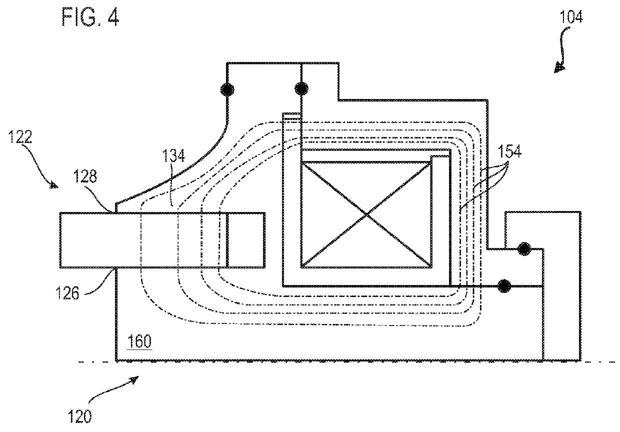
[0065]FIG. 4 shows an electromagnetic actuator 104 according to a second embodiment of the invention. This FIG. 4 repeats the numbering of the preceding figures for identical or similar elements, but the numbering is incremented by 100. Specific numbers are used for elements specific to this embodiment.

[0066]The electromagnetic actuator 104 may be substantially identical to that of FIG. 3, but differs from it in that it has only a single annular chamfer 134, which radially delimits the outer radial gap 128 for example. The inner radial gap 126 may be delimited by a cylindrical portion 160 which extends the casing 120 towards the plunger 122. The circuit therefore has more ferromagnetic material carrying the magnetic flux lines 154.

Example

[0067]FIG. 5 shows an electromagnetic actuator 204 according to a third embodiment of the invention. This FIG. 5 repeats the numbering of the preceding figures for identical or similar elements, but the numbering is incremented by 200. Specific numbers are used for elements specific to this embodiment.

[0068]The electromagnetic actuator 204 according to the second embodiment may be substantially identical to that of FIG. 4, but differs from it in the axial offset of the radial gaps (226; 228). The cylindrical portion 260 may continue beyond the outer gap 228, and further extend the casing 220. The plunger 222 may have an optional chamfer 262, formed for example on the tubular portion 230 of the plunger 222. This chamfer 262 is directed radially inwards, that is to say towards the cylindrical portion 260. Here again, a greater amount of ferromagnetic material becomes available.

Example

[0069]FIG. 6 shows an electromagnetic actuator 304 according to a fourth embodiment of the invention. This FIG. 6 repeats the numbering of the preceding figures for identical or similar elements, but the numbering is incremented by 300. Specific numbers are used for elements specific to this embodiment.

[0070]The electromagnetic actuator 304 according to the fourth embodiment may be substantially identical to that of FIG. 3. It differs from it in its casing 320, which is then split circularly between the radial gaps (326; 328), and in the partition 356 which is formed by the coil support 364. Additional gaskets 350 are added. The core 344 is divided circularly into an inner bar 366 surrounded by an outer ring 368, which radially delimit the inner radial gap 326 and the outer radial gap 328 respectively. This separation makes it possible to use different materials in the magnetic circuit. The bar 366 and the ring 368 may be connected via the support 364 which may be made of a ferromag...


PUM


Abstract

The invention proposes a proportional electromagnetic actuator comprising: a magnetic casing; an electromagnetic plunger movable relative to the casing and having a first axial half; a first radial gap and a second radial gap which are each formed radially between the plunger and the casing, and which are positioned axially at the first axial half of the plunger. These gaps (26; 28) are formed by concentric annular chamfers (32; 34). The invention also proposes a three-way valve for turbojet oil, which is actuated by an electromagnetic actuator with double chamfered gaps.

Description

TECHNICAL FIELD[0001]The invention relates to the field of electromagnetic actuators. More precisely, the invention concerns a proportional electromagnetic actuator in which the magnetic circuit is chamfered. The invention also relates to a valve equipped with an electromagnetic actuator.PRIOR ART[0002]A proportional electromagnetic actuator may be used in order to precisely control the position of the plunger and provide progressive mechanical operation. For this purpose, such an actuator has a magnetic circuit with a chamfer formed on the plunger. The circular point of this chamfer closes the magnetic circuit around the core of the magnetic circuit, and makes use of magnetic saturation phenomena in order to modulate the force generated by the plunger as a function of the electrical power supply to the electromagnetic coil. Because a proportional spring is used, the proportional force of the plunger is converted to a proportional displacement as a function of the supply current. Th...

Claims


Application Information

Patent Timeline
IPC IPC(8): F16K31/06
CPCF16K31/0675F16K31/0668F16K31/061H01F7/081H01F7/128H01F7/1638H01F2007/083H01F2007/086
Inventor PAULUS, NICOLAS
Owner SAFRAN AERO BOOSTERS SA
Why Eureka
Try Eureka