
Firearm single-shot bolt catch assembly and method of operation

a single-shot, bolt-catching technology, applied in the direction of weapons, firing/trigger mechanisms, weapon components, etc., can solve the problem of not converting automatic rifles to single-shot mod

Active Publication Date: 2018-04-12
BORDERS BRIAN T
View PDF0 Cites 19 Cited by
  • Summary
  • Abstract
  • Description
  • Claims
  • Application Information

AI Technical Summary

Benefits of technology

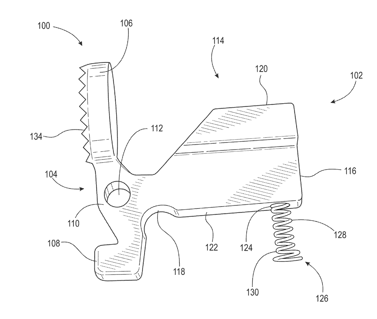
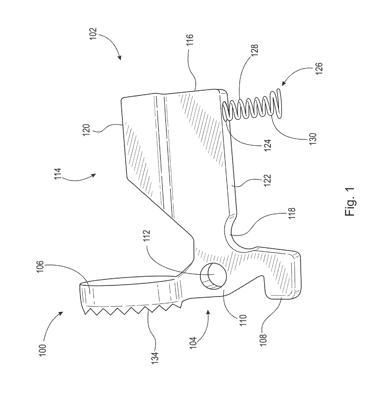
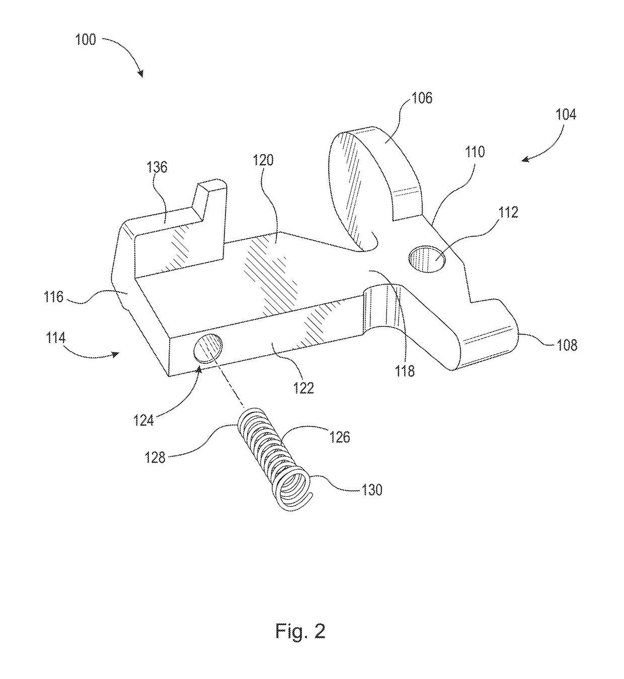
The disclosure is about a firearm single-shot bolt catch assembly and how it works. The assembly uses a tensioned spring and a plate to catch the bolt and prevent it from moving backward when fired. This prevents the firearm from automatically recoiling and allows for a single-shot mode. The assembly is easy to install and inexpensive to manufacture. The technical effects are improved reliability, safety, and a more efficient and reliable firearm.

Problems solved by technology

The problem with these bolt catch devices is that they do not convert automatic rifles to single-shot mode by automating the restriction of forward recoil by the bolt.
This restrictive disposition of the plate restricts the bolt carrier group at a rearward end of the firearm.

Method used


Image

  • Firearm single-shot bolt catch assembly and method of operation
  • Firearm single-shot bolt catch assembly and method of operation
  • Firearm single-shot bolt catch assembly and method of operation

Examples


Embodiment Construction

[0028]The following detailed description is merely exemplary in nature and is not intended to limit the described embodiments or the application and uses of the described embodiments. As used herein, the word “exemplary” or “illustrative” means “serving as an example, instance, or illustration.” Any implementation described herein as “exemplary” or “illustrative” is not necessarily to be construed as preferred or advantageous over other implementations. All of the implementations described below are exemplary implementations provided to enable persons skilled in the art to make or use the embodiments of the disclosure and are not intended to limit the scope of the disclosure, which is defined by the claims. For purposes of description herein, the terms “upper,”“lower,”“left,”“rear,”“right,”“front,”“vertical,”“horizontal,” and derivatives thereof shall relate to the invention as oriented in FIG. 1. Furthermore, there is no intention to be bound by any expressed or implied theory pres...


PUM


Abstract

A firearm single-shot bolt catch assembly and method of operation. The automatic firearm single-shot bolt catch assembly uses a tensioned spring that operates with a bolt catch. The tension from the spring works to pivotally articulate a plate in the bolt catch to a catch position, which restricts the recoiling bolt carrier group in linear path of the firearm. The tension from the spring presses the plate upwardly into the linear path to restrict the passage of, and hold, the bolt carrier group towards the rearward end of the firearm. This restriction of movement inhibits automated recoiling responses from the bolt carrier group, consequently creating a single-shot mode by disabling automated firing sequence of the firearm. Applying force to a lever that forms in the bolt catch overcomes the spring bias to displace the plate out of the linear path followed by the bolt carrier.

Description

CROSS REFERENCE OF RELATED APPLICATIONS[0001]This application claims the benefits of U.S. provisional application No. 62 / 404,799, filed Oct. 6, 2016 and entitled SINGLE SHOT BOLT CATCH ASSEMBLY, which provisional application is incorporated by reference herein in its entirety.FIELD OF THE INVENTION[0002]The present invention relates generally to a firearm single-shot bolt catch assembly and method of operation. More so, the automatic firearm single-shot bolt catch assembly utilizes a tensioned spring that operates with a bolt catch; whereby the tension from the spring works to pivotally articulate a plate in the bolt catch to a catch position, which restricts the recoiling bolt carrier group in linear path of the firearm; whereby the tension from the spring presses the plate upwardly into the linear path to restrict the passage of, and hold, the bolt carrier group towards the rearward end of the firearm; whereby the restriction of movement inhibits automated recoiling responses from...

Claims


Application Information

Patent Timeline
Patent Type & Authority Applications(United States)
IPC IPC(8): F41A17/42F41A3/72
CPCF41A17/42F41A3/72F41A19/46
Inventor BORDERS, BRIAN T.
Owner BORDERS BRIAN T
Learn More