Oil passage structure for power transmission device

a technology of power transmission device and oil passage, which is applied in the direction of gearing details, mechanical equipment, gearing, etc., can solve the problems of large oil pressure loss and long oil passage length, and achieve the effect of reducing oil pressure loss and reducing oil passage length

Active Publication Date: 2018-04-19
TOYOTA JIDOSHA KK
View PDF2 Cites 29 Cited by
  • Summary
  • Abstract
  • Description
  • Claims
  • Application Information

AI Technical Summary

Benefits of technology

[0029]In the disclosure, oil can be pumped via the oil passage provided in the baffle plate. Accordingly, it is possible to make the oil passage length of the supply oil passage shorter than that of an oil passage that bypasses the baffle plate, and the pressure loss of oil caused by the oil passage length can also be reduced.

Problems solved by technology

For example, in a case where the differential gear mechanism is used as a portion to which an oil is supplied, the supply pipe is installed so as to bypass the baffle plate described in JP 2016-41979 A. In this way, in the configuration in which the supply pipe is provided inside the case, there is a possibility that oil passage length may become long and the pressure loss of oil may become large.

Method used


Image

  • Oil passage structure for power transmission device
  • Oil passage structure for power transmission device
  • Oil passage structure for power transmission device

Examples


first embodiment

[0039]1. Overall Configuration

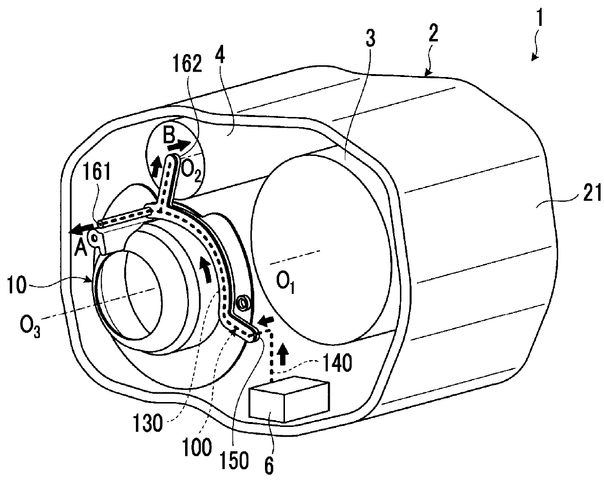
[0040]FIG. 1 is a schematic view for illustrating an oil passage structure for a power transmission device in a first embodiment. In addition, for convenience of description, oil passages (a supply pipe 300 of the related art, an oil passage 200 that is the shortest path), which are not included in the embodiment, are illustrated in FIG. 1.

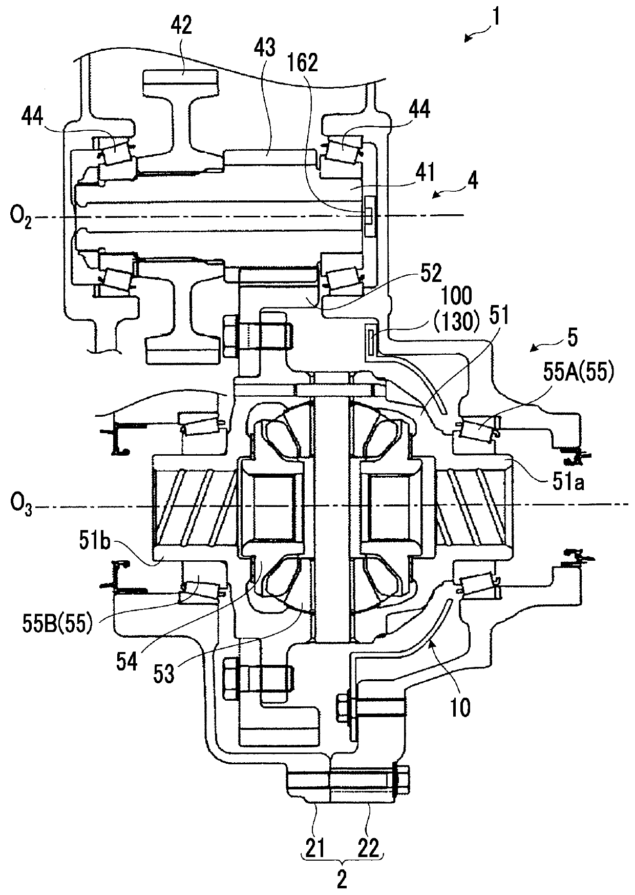
[0041]1-1. Power Transmission Device

[0042]A power transmission device 1 is a mechanism that is mounted on a vehicle in a state where the power transmission device is accommodated in a case 2 and that transmits the power, which is output from an engine, to the driving wheels. The power transmission device 1 illustrated in FIG. 1 is mounted on a front engine front drive type vehicle (FF vehicle), and includes a transmission 3, a counter gear mechanism 4, and a differential gear mechanism 5, which are accommodated in the case 2. That is, the case 2 is a transaxle case (T / A case) that accommodates the transmission 3 and t...

modification example of first embodiment

[0086]As a modification example of a first embodiment, the baffle plate 10 may be provided with a plurality of independent plate oil passages. As an example of the modification example, a baffle plate 10 in which two independent plate oil passages are provided is illustrated in FIG. 6. In addition, in the description of the modification example, the description of the same components as those in the first embodiment will be omitted, and the reference signs of the components will be used.

[0087]FIG. 6 is a plan view for illustrating the plate oil passages in the modification example of the first embodiment. As illustrated in FIG. 6, a second plate oil passage 170 is provided in the baffle plate 10 of the modification example separately from the plate oil passage 130. Moreover, a second supply port 171 and a fourth discharge port 172 are formed in the baffle plate 10. The oil supplied from the second supply port 171 flows into the second plate oil passage 170, and the oil is discharged...

second embodiment

[0088]5. Structure of Baffle Plate in Second Embodiment

[0089]Next, an oil passage structure for a power transmission device in a second embodiment will be described with reference to FIG. 7. In the second embodiment, the baffle plate 10 is formed by integrating separately molded members with each other, unlike the first embodiment. In addition, in the description, the description of the same components as those of the first embodiment will be omitted, and the reference signs of the components will be used.

[0090]FIG. 7 is a perspective view schematically illustrating the baffle plate 10 in the second embodiment. As illustrated in FIG. 7, the baffle plate 10 of the second embodiment has a structure in which a plate body 110 and a tubular member 120 are integrated with each other.

[0091]5-1. Plate Body

[0092]The plate body 110 is a plate-shaped member made of resin and is a member (first member) that constitutes a main constituent of the baffle plate 10. For example, the plate body 110 i...


PUM

PropertyMeasurementUnit
hydraulic pressureaaaaaaaaaa
pressure lossaaaaaaaaaa
lengthaaaaaaaaaa

Abstract

In an oil passage structure for a power transmission device including a case provided to accommodate a power transmission device, a baffle plate attached to an inner wall of the case, and an oil pump, the oil passage structure includes a supply oil passage through which oil is pumped from the oil pump to an oil supply destination via the baffle plate. A plate oil passage, which constitutes a portion of the supply oil passage, a supply port, which allows the oil discharged from the oil pump to flow into the plate oil passage through the supply port, and a first discharge port, which allows the oil supplied to the oil supply destination to be discharged through the first discharge port, are formed in the baffle plate.

Description

INCORPORATION BY REFERENCE[0001]The disclosure of Japanese Patent Application No. 2016-202759 filed on Oct. 14, 2016 including the specification, drawings and abstract is incorporated herein by reference in its entirety.BACKGROUND1. Technical Field[0002]The present disclosure relates to an oil passage structure for a power transmission device.2. Description of Related Art[0003]Lubrication-needing sites that need lubrication using oil, such as engagement parts of gears and bearings, are provided inside a case provided to accommodate a power transmission device. As methods of supplying oil to the lubrication-needing sites, a method of pumping oil with an oil pump and oil passages, and a method (scooping lubrication) of scooping oil with a differential ring gear of a differential gear mechanism are known.[0004]Japanese Unexamined Patent Application Publication No. 09-026018 (JP 09-026018 A) discloses, as the method of pumping oil, connecting a supply pipe to oil passages formed in a ca...

Claims


Application Information

Patent Timeline
Patent Type & Authority Applications(United States)
IPC IPC(8): F16H57/04F16H48/08
CPCF16H57/0423F16H48/08F16H57/0457F16H57/0471F16H57/0483F16H57/0421F16H57/0434B29C43/00F16H57/032F16H57/0445F16H57/0446F16H2057/02091F16H2057/02095F16H2061/0037F16H57/04
Inventor KAWAKAMI, TAKAHOTABUCHI, MOTOKI
Owner TOYOTA JIDOSHA KK
Why Eureka
Try Eureka