Liquid ejection head and image recording apparatus

a liquid ejection head and image recording technology, applied in the direction of printing, inking apparatus, other printing apparatus, etc., can solve problems such as liquid ejection failures, and achieve the effect of preventing the formation of air bubbles and viscosity of liquid

Inactive Publication Date: 2006-08-15
FUJIFILM CORP
View PDF5 Cites 14 Cited by
  • Summary
  • Abstract
  • Description
  • Claims
  • Application Information

AI Technical Summary

Benefits of technology

[0007]The present invention has been contrived in view of such circumstances, and an object thereof is to provide a structure of a liquid ejection head and an image recording apparatus using the head, whereby generation of air bubbles in the head, and particularly in the common flow passage, can be avoided, and pressure loss caused by reflux of ink from the supply port into the common flow passage can be suppressed.

Problems solved by technology

On the other hand, if the temperature of the pressure chamber is lower than the temperature of the common flow passage, then air bubbles inside the pressure chamber, which may cause liquid ejection failures, can be made to dissolve into the liquid.

Method used


Image

  • Liquid ejection head and image recording apparatus
  • Liquid ejection head and image recording apparatus
  • Liquid ejection head and image recording apparatus

Examples


first embodiment

the Present Invention

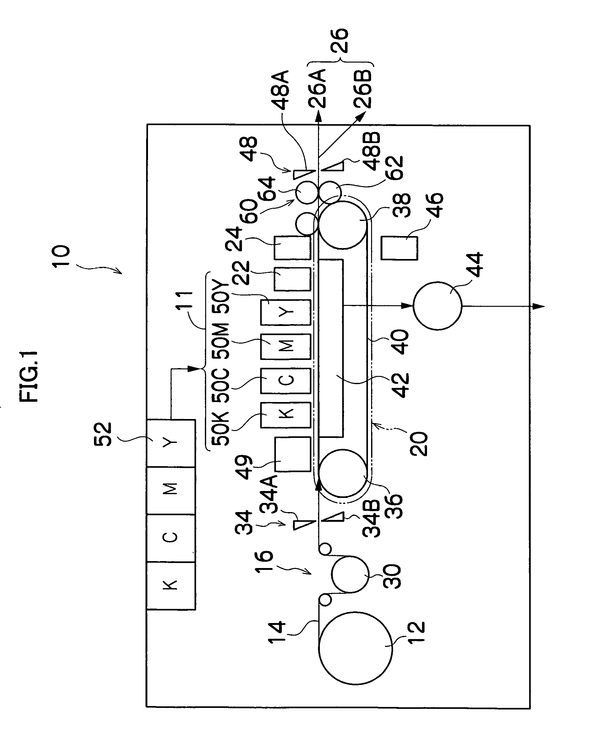
[0040]FIG. 1 is a general schematic drawing of an inkjet recording apparatus according to an embodiment of the present invention.

[0041]The inkjet recording apparatus 10 is a printer to record data of image and the like by ejecting the ink liquid droplet onto the recording paper 14, and comprises: a paper supply unit 12 for supplying recording paper 14; a decurling unit 16 for removing curl in the recording paper 14; a print unit 11 having a plurality of print heads 50K, 50C, 50M, and 50Y for ink colors of black (K), cyan (C), magenta (M), and yellow (Y), respectively; a suction belt conveyance unit 20 disposed facing the nozzle face (ink-droplet ejection face) of the print unit 11, for conveying the recording paper 14 while keeping the recording paper 14 flat; a post-drying unit 24 for applying after-treatment to the printed recording paper 14; and a print determination unit 22 for reading the printed result produced by the print unit 11; and a paper output unit...

second embodiment

the Present Invention

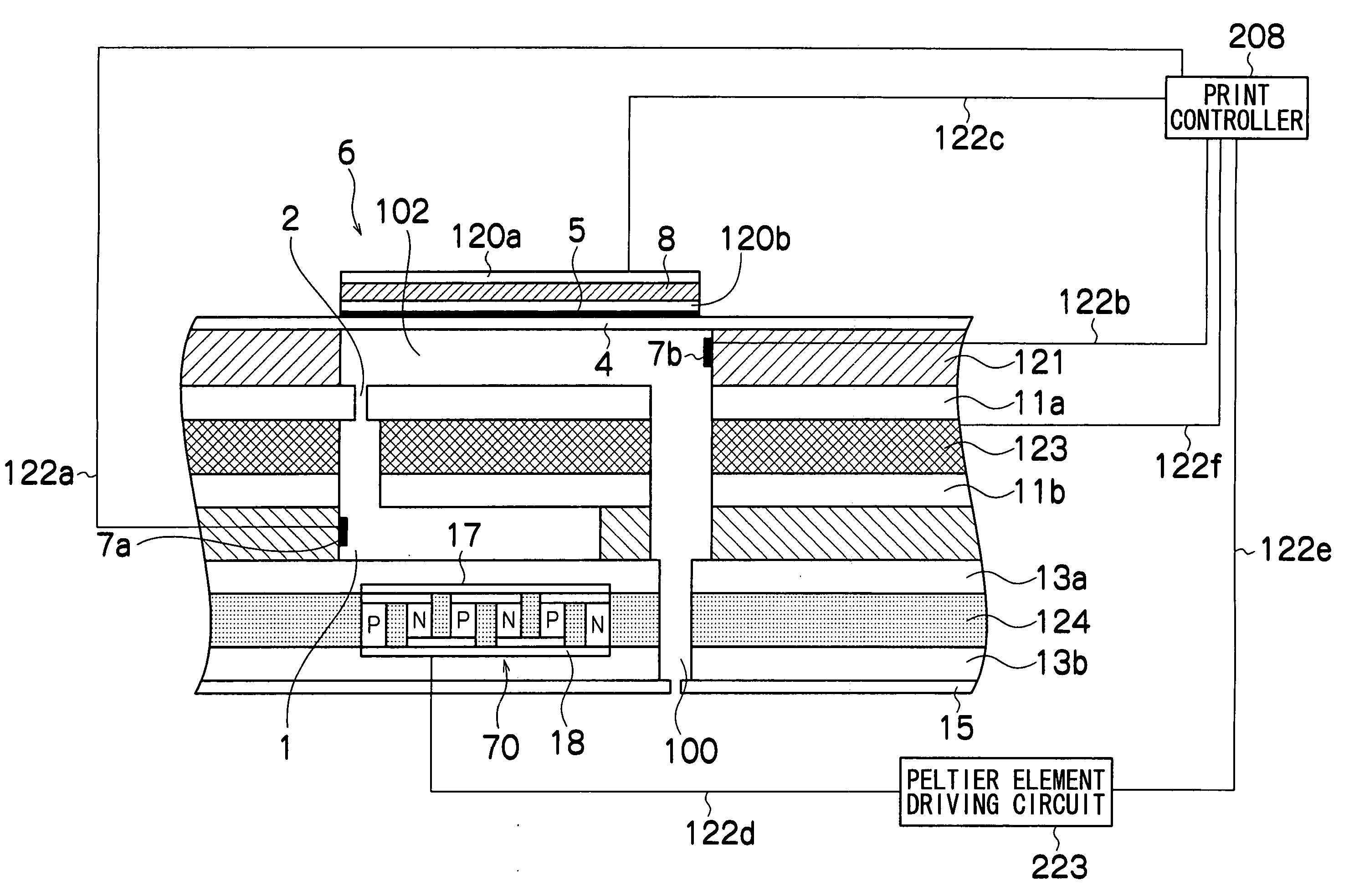
[0106]FIG. 11 is a general schematic drawing of an inkjet head according to another preferred embodiment of the present invention. Parts which are the same as those in the first embodiment are labeled with the same reference numerals as FIG. 6. In the present embodiment, in contrast to the first embodiment, a Peltier element 70 is provided in a layer between the pressure chamber 102 and the common flow passage 1. A first joint section 17 of the Peltier element 70 is joined to the lower face of the pressure chamber 102 via the ink supply port forming substrate 11a, and a second joint section 18 of the Peltier element 70 is joined to the upper face of the common flow passage 1 via the common flow passage upper substrate 11b. The regions of the Peltier element 70 apart from the first joint section 17 and the second joint section 18 are surrounded by a thermal insulating member 124. The heater 123 is bonded in a layer between the nozzle plate 15 and the common flow ...

third embodiment

the Present Invention

[0111]FIG. 12 is a general schematic drawing of an inkjet head according to another preferred embodiment of the present invention. Parts which are the same as those in the first embodiment are labeled with the same reference numerals as FIG. 6. In this embodiment, in contrast to the first embodiment, the first joint section 17 of the Peltier element 70 is joined to the lower face of the pressure chamber 102, via the ink supply port forming substrate 11a. The second joint section 18 of the Peltier element 70 is joined to the upper face of a thermal conducting member 19 made of SUS (Steel Use Stainless), or the like. The regions of the Peltier element 70 apart from the first joint section 17 and the second joint section 18 are surrounded by a thermal insulating member 124. The lower face of the thermal conducting member 19 is joined to a nozzle plate 15 in which the ejection port of the nozzle 100 is provided.

[0112]The inkjet head according to the present embodime...


PUM


Abstract

The liquid ejection head comprises: a plurality of nozzles which eject droplets of liquid; a plurality of pressure chambers which are respectively connected to the nozzles; a common flow passage which supplies the liquid to the pressure chambers; a plurality of ejection devices which respectively cause the liquid in the pressure chambers to be ejected from the nozzles; a temperature differential generating device which generates a temperature differential between the common flow passage and each of the pressure chambers; a common flow passage temperature determining device which determines temperature of the common flow passage; a pressure chamber temperature determining device which determines temperature of each of the pressure chambers; and a control device which controls the temperature differential generating device in accordance with the temperature of the common flow passage and the temperature of each of the pressure chambers, in such a manner that the temperature differential between the common flow passage and each of the pressure chambers reaches a prescribed temperature differential.

Description

BACKGROUND OF THE INVENTION[0001]1. Field of the Invention[0002]The present invention relates to a liquid discharge head and an image recording apparatus, and more particularly to temperature adjustment in a liquid ejection head.[0003]2. Description of the Related Art[0004]An inkjet head (recording head) has a composition in which ink is supplied to pressure chambers connected to nozzles, and liquid droplets are ejected from the nozzles by applying a pressure change to the liquid inside the pressure chambers. If there is an air bubble inside a pressure chamber, the pressure required for ejection is not transmitted to the ink, and an ejection error thereby arises. In order to prevent ejection errors of this kind, an operation is performed in order to suction the ink containing air bubbles inside the pressure chambers and expel the air bubbles together with the ink (namely, a “suction operation”). However, there is a problem in that the amount of ink consumed increases when a suction ...

Claims


Application Information

Patent Timeline
Patent Type & Authority Patents(United States)
IPC IPC(8): B41J29/38B41J2/045B41J2/14
CPCB41J2/04528B41J2/04563B41J2/14233B41J2/04581B41J2202/20B41J2002/14459
Inventor TAKATSUKA, TSUTOMU
Owner FUJIFILM CORP
Why Eureka
Try Eureka