Method and device for the adaptive regulation of a positive end-expiratory pressure (PEEP)

a positive end-expiratory pressure and adaptive regulation technology, applied in medical science, diagnostics, other medical devices, etc., can solve the problems of not being able to detect air trapping by ventilators, so-called air trapping, and damage to the respiratory organs of patients

Active Publication Date: 2018-04-26
DRAGERWERK AG
View PDF7 Cites 8 Cited by
  • Summary
  • Abstract
  • Description
  • Claims
  • Application Information

AI Technical Summary

Benefits of technology

[0009]An object of the present invention is therefore to provide a device and...

Problems solved by technology

This may lead to so-called air trapping.
This may lead to damage to the respiratory organs of the patient.
Furthermore, air trapping is not detected by these ventilators.
Air trapping cannot be avoided with this method either.
This is because the residual volume in the lungs cannot be monitored during the exhalation.
In general, the expiratory flow cannot be infl...

Method used


Image

  • Method and device for the adaptive regulation of a positive  end-expiratory pressure (PEEP)
  • Method and device for the adaptive regulation of a positive  end-expiratory pressure (PEEP)
  • Method and device for the adaptive regulation of a positive  end-expiratory pressure (PEEP)

Examples


Embodiment Construction

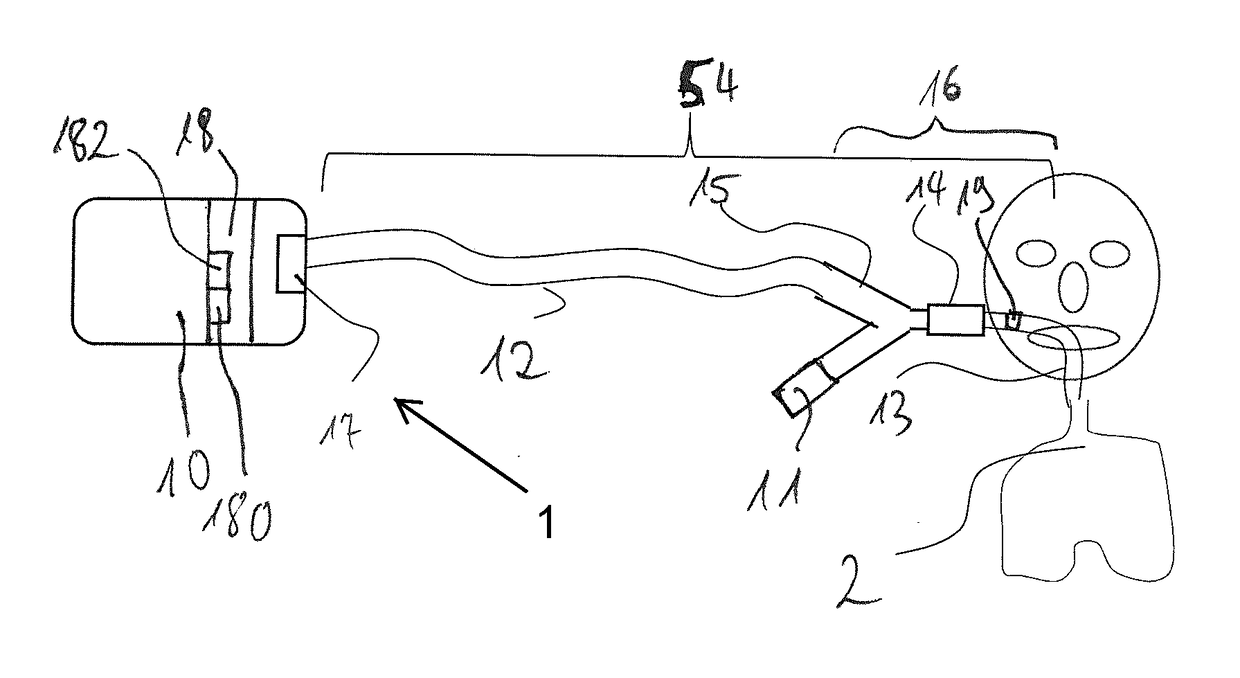
[0033]Referring to the drawings, a ventilator is designated in its entirety by the reference number 1 in FIG. 1. It has a blower unit 10 with a fan 17, which blower unit 10 is connected to a patient 2 via a user interface 16.

[0034]The user interface 16 comprises a tube 13, which is connected to a gas flow-measuring unit 14, a Y-piece 15, which is connected with one end to the gas flow-measuring unit 14, and an exhalation valve 11, which is connected to a second end of the Y-piece 15. The last end of the Y-piece 15 is fluid-communicatingly connected to a fan 17 of the blower unit 10 via a tube 12.

[0035]As an alternative, the user interface 16 may be configured as a mask, as a nasal mask or also in another form, the user interface 16 always comprising an exhalation valve 11.

[0036]The ventilator 1 further comprises a control device 18, which transmits control signals to the exhalation valve 11 and to the fan 17, as well as received measured signals from the gas flow-measuring unit 14. ...


PUM


Abstract

A method controls an expiratory gas flow at a user interface (16) of a ventilator (1) wherein the user interface (16) has an exhalation valve (11), which provides a positive end-expiratory pressure (PEEP). The method includes the following steps during a phase of exhalation: changing the positive end-expiratory pressure from a basic PEEP value (31) with the exhalation valve (11); returning the positive end-expiratory pressure to the basic PEEP value (31) with the exhalation valve (11); and determining an exhalation parameter. The method permits an adaptive change in the expiratory flow during the exhalation. Air trapping can be avoided, and it is possible to respond to changed exhalation parameters within one and the same phase of exhalation.

Description

CROSS REFERENCE TO RELATED APPLICATIONS[0001]This application claims the benefit of priority under 35 U.S.C. § 119 of German Application 10 2016 012 824.0, filed Oct. 25, 2016, the entire contents of which are incorporated herein by reference.FIELD OF THE INVENTION[0002]The present invention pertains to a method for controlling expiratory gas flow.BACKGROUND OF THE INVENTION[0003]Ventilators (also known as respirators) are used to support the ventilation of patients. The ventilators introduce breathing air into the lungs of the patient and also remove the air from the lungs, e.g., in case of mandatory ventilation. In order not to damage the patient's lungs, some parameters of the lungs and of the tube system, with which the breathing air is transported from the device to the patient and optionally back, must be known to the ventilator. Insofar as available, among other things, pneumatic resistances of the device, the compliance of the device, the compliance of the lungs as well as t...

Claims


Application Information

Patent Timeline
IPC IPC(8): A61M16/20A61M16/00A61M16/18A61M16/22A61B5/091
CPCA61M16/20A61M16/0009A61M16/18A61M16/22A61B5/091A61M2016/0021A61M2016/0039A61M2016/0042A61M2016/0413A61M2016/0027A61M2016/003A61M16/0003A61B5/08A61M2205/33A61B5/087A61M2016/0036A61M2230/46A61M16/0833A61M16/205A61M2230/005
Inventor HANSMANN, HANS-ULLRICHHILTAWSKY, KARSTEN
Owner DRAGERWERK AG
Why Eureka
Try Eureka