Actuator

Inactive Publication Date: 2018-04-26
SAF HOLLAND GMBH
View PDF4 Cites 0 Cited by
  • Summary
  • Abstract
  • Description
  • Claims
  • Application Information

AI Technical Summary

Benefits of technology

[0012]The spacer element particularly preferably has a third engagement section which can be brought into positively locking engagement with the securing section. The third engagement section of the spacer element is preferably configured as a bore or groove, it being possible for a securing section which is provided on a securing ring or circlip to engage into the corresponding groove, whereas an engagement section which is configured as a bore is designed for the engagement of a securing section which is configured on a pin or securing peg. The third engagement section is advantageously configured on the spacer element in such a way that a commercially available body, such as a circlip, can be configured with the securing section, in order to protect the spacer element against movement and to hold it in the first position. The costs for an actuating unit within the context of the present invention can therefore be reduced considerably.
[0013]Moreover, the securing section is preferably configured on a clip element which, having been brought into positively locking engagement with the shoe unit, secures the spacer element against rotation about the actuating axis. The clip element can preferably be configured as a U-shaped body which firstly has engagement faces for positively locking engagement with the spacer element and secondly also preferably has engagement faces for positively locking engagement with an accordingly corresponding geometry of the shoe unit, in order to particularly preferably secure the spacer element against rotation about the actuating axis relative to the shoe unit. In particular, an undercut geometry can preferably be provided on the clip element, which undercut geometry can be overcome by a user with the application of a force which can be generated manually, in order for it to be possible to “clip” the clip element with the securing section into the corresponding securing position, and in order for it also to be possible to remove it from said position again without a further tool.
[0014]As an alternative, the securing section can preferably be fixed on the spacer element or can be configured in one piece with the spacer element, and can have a geometry which differs from the rotational geometry in relation to the actuating axis, it being possible for the securing section to be moved by way of movement along the actuating axis into a position, in which it engages in a corresponding section on the shoe unit and secures the spacer element against rotation about the actuating axis. As an alternative or in addition to a securing section which is configured on a separate element, the securing section can also be configured as a geometry on the spacer element, which geometry correspondingly differs from the rotational geometry. Here, for example, an external square which is simple to produce may be suitable, which external square can be brought into engagement with a corresponding section of the shoe unit, which section is configured as an internal square bore, the spacer element being secured against rotation about the actuating axis relative to the shoe unit. It goes without saying that, as an alternative to the spacer element being fixed on the shoe unit, securing of the spacer element on the supporting unit is also possible by way of a correspondingly configured securing section.
[0015]Furthermore, a holding element is preferably provided, in order to secure the securing section against movement along the actuating axis. In the case, in particular, in which the securing section is configured to secure the spacer element against rotation about the actuating axis, a holding element, such as a splint or a clamping ring, is preferably provided which prevents the securing section from sliding out of the position, in which it secures the spacer element against rotation relative to the shoe unit. The advantage of said embodiment is that the holding element has to absorb only relatively low forces, since the main load of the securing action is assumed by the securing section itself, and the holdin

Problems solved by technology

In the case of the known mechanical adjusting devices, in particular, the actuating screws of the actuating unit can often be reached only wi

Method used


Image

  • Actuator
  • Actuator
  • Actuator

Examples


Example

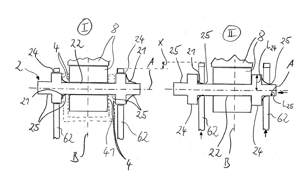
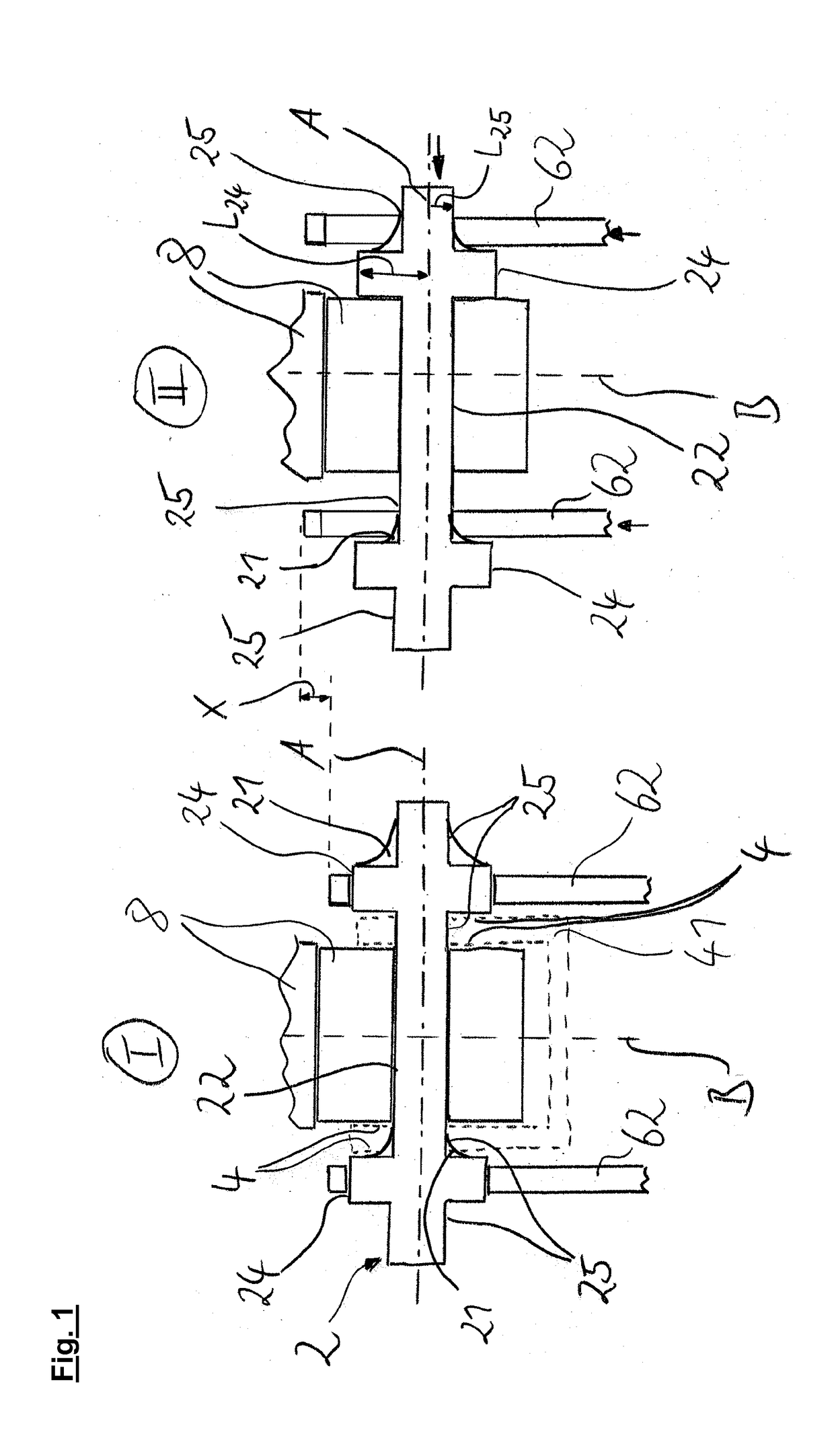
[0030]FIG. 1 shows two views of one embodiment of the actuating unit according to the invention, the left-hand part (identified by I) of FIG. 1 showing the actuating unit in the state, in which the spacer element 2 is situated in its first position I. The view on the right which is identified by II shows the spacer element 2 in its second position II. The spacer element 2 has a first engagement section 24 and a second engagement section 25. As shown in the preferred embodiment, the spacer element 2 preferably has two first engagement sections 24 and four second engagement sections 25. Furthermore, the spacer element 2 preferably has a holding section 22 which preferably has the same diameter in the present embodiment as the second engagement sections 25. The shoe unit 6 preferably comprises two shoe webs 62 which are provided with cutouts which can be brought into engagement in each case with the first engagement section 24 or with a second engagement section 25 of the spacer elemen...


PUM


Abstract

This relates to an actuating unit, in particular for a drum brake, comprising a spacer element which can be fixed on a shoe unit or on a supporting unit, the spacer element having a holding section, via which it can be secured against movement along an activating axis relative to the shoe unit or the supporting unit, the spacer element having a first engagement section which is supported on the respective other one of the units comprising the shoe unit or the supporting unit in a first position of the spacer element, it being possible for the spacer element to be moved into a second position, in which the first engagement section is out of engagement with the shoe unit and the supporting unit, the spacer element spacing the shoe unit and the supporting unit further apart from one another in the first position than in the second position.

Description

BACKGROUND OF THE INVENTION[0001]The present application relates to an actuating unit for use in brake systems, in particular for commercial vehicles, and to a method for dismantling a brake system.[0002]Actuating units are known in the field of brake systems for commercial vehicles; it has thus proven advantageous to use adjusting and resetting devices in the brake actuating systems of commercial vehicles, which adjusting and resetting devices compensate for the wear of the brake shoes or the brake linings and can be reset again into the original starting position by way of the resetting function during the replacement of the brake linings. In the case of the actuating units which are known from the prior art, it has been necessary up to now to utilize the sometimes very complicated restoring mechanism which can be difficult to reach in order to dismantle the brake shoes, in order for it to be possible to set a sufficient play, by way of which the brake shoes or the brake linings c...

Claims


Application Information

Patent Timeline
IPC IPC(8): F16D65/09F16D65/22
CPCF16D65/09F16D65/22F16D2125/582F16D2125/22
Inventor DREWES, OLAFMARSCHNER, OLIVER
Owner SAF HOLLAND GMBH
Why Eureka
Try Eureka