Pressure sensor

a pressure sensor and sensor technology, applied in the field of pressure sensors, can solve the problems of increasing the number of causes of errors, inability to solve the detection error of pressure due to thermal strain, and inability to solve the thermal deformation of the tip portion, so as to reduce the number of parts, suppress the sensitivity of the sensor with respect to temperature variation, and simplify the effect of the structur

Active Publication Date: 2018-04-26
MIKUNI CORP
View PDF7 Cites 3 Cited by
  • Summary
  • Abstract
  • Description
  • Claims
  • Application Information

AI Technical Summary

Benefits of technology

[0029]According to the pressure sensor having the above-mentioned configuration, variation in sensor sensitivity with respect to temperature variation can be suppressed by suppressing a measurement error due to thermal deformation or the like while accomplishing simplification of a structure, reduction in the number of parts, reduction in the number of processing operations, reduction in cost, and so on. Therefore, it is possible to obtain a pressure sensor capable of accurately detecting a pressure of a pressured medium such as a combustion gas or the like in a combustion chamber of an engine.

Problems solved by technology

Therefore, there are more causes of an error due to thermal deformation.
In addition, since deformation in the axial direction due to the thermal expansion of the diaphragm and deformation in the axial direction due to the thermal expansion of the housing are not oriented so as to cancel each other out, the detection error in the pressure due to the thermal strain cannot be solved.
In addition, since the tip portion of the housing exposed in the combustion chamber has different thicknesses and has an annular concave portion, thermal deformation of the tip portion is not simple.
Therefore, the error due to thermal deformation may be promoted.
Further, since the number of parts is great, and various kinds of processing are necessary, an increase in costs occurs.
Therefore, there are more causes of an error due to thermal deformation.
In addition, when the rod expands toward the combustion chamber due to heating, the diaphragm also moves or thermally expands toward the combustion chamber together therewith, and the detection error in the pressure due to the thermal strain cannot be solved.
Further, since the number of parts is great, and various kinds of processing are necessary, an increase in costs occurs.

Method used


Image

  • Pressure sensor
  • Pressure sensor
  • Pressure sensor

Examples


Embodiment Construction

[0038]Hereinafter, an embodiment of the present invention will be described with reference to the accompanying drawings.

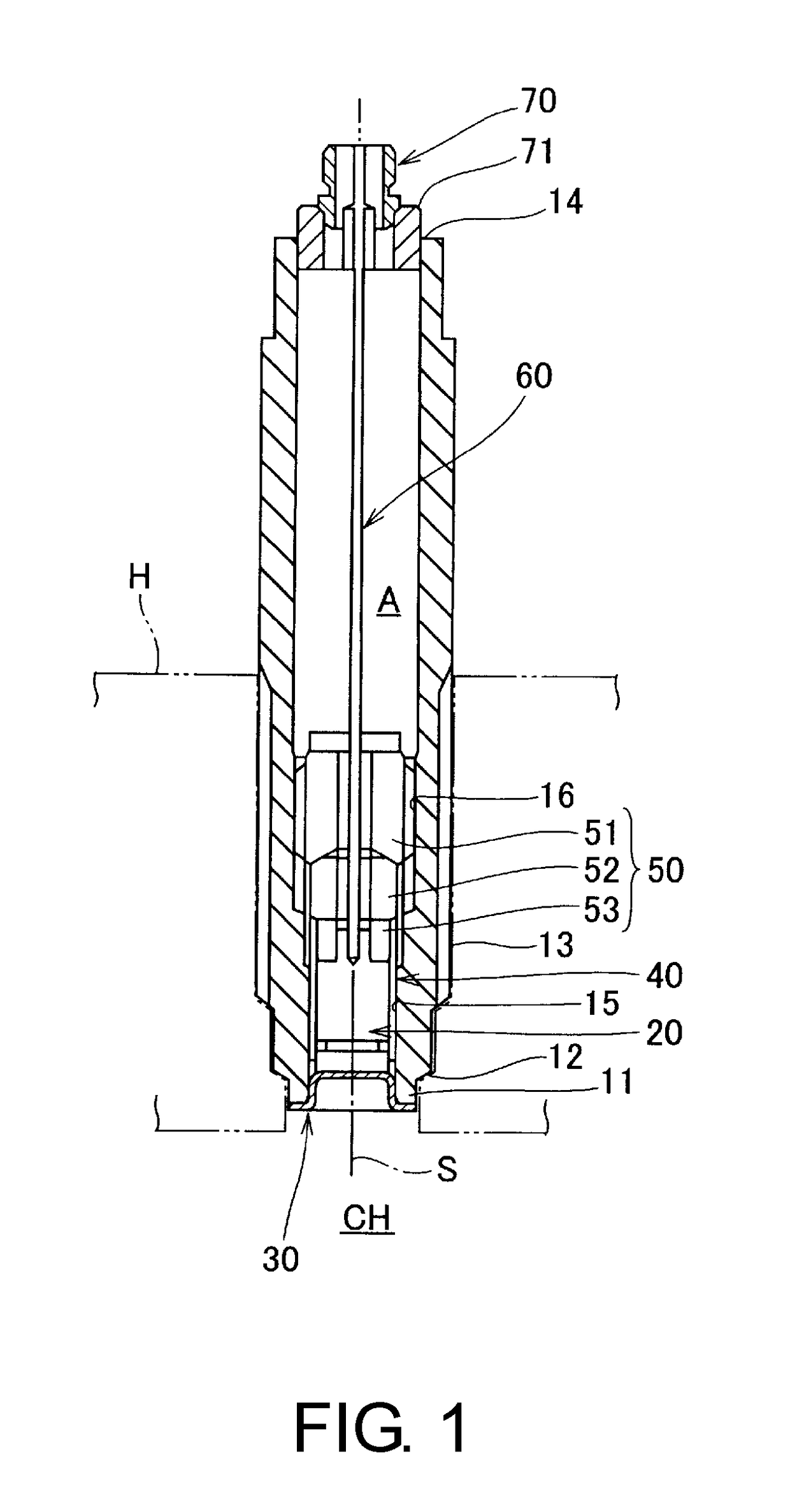
[0039]A pressure sensor according to the embodiment is attached to a cylinder head H of an engine to detect a pressure of a combustion gas (a pressured medium) in a combustion chamber of the engine.

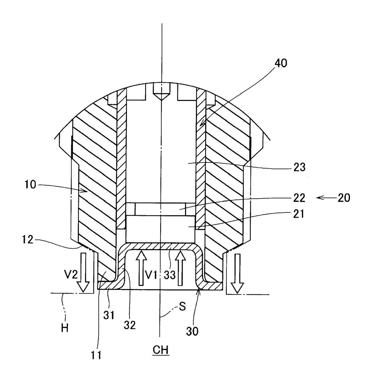
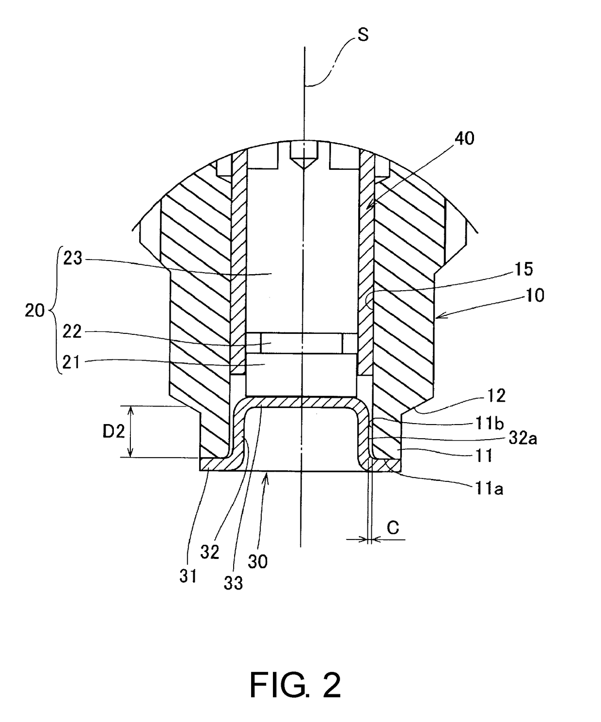
[0040]As shown in FIGS. 1 and 2, the pressure sensor includes a housing 10 extending in an axis S direction, an output measurement unit 20 accommodated in the housing 10, a diaphragm 30 serving as a pressure transmission member configured to close an accommodating space of the output measurement unit 20 and transmit a pressure of a combustion gas applied in the axis S direction to the output measurement unit 20, a tubular insulating member 40 configured to provide electrical insulation between a first electrode 21 and a second electrode 23 of the output measurement unit 20, a pressing member 50 disposed in the housing 10 and configured to press and hold the output measur...


PUM

PropertyMeasurementUnit
folding angleaaaaaaaaaa
depthaaaaaaaaaa
folding angleaaaaaaaaaa

Abstract

This pressure sensor is equipped with: a housing (10) having a tip tubular portion (11) that lengthens in the direction of an axis (S) and is exposed to a pressure medium; an output measurement unit (20) that includes a piezoelectric member (22) and is housed inside the housing; and a pressure transmission member for occluding the space for storing the output measurement unit in the housing, and transmitting the pressure from the pressure medium imparted in the axial direction to the output measurement unit. The pressure transmission member is a bottomed diaphragm having: an inner tubular portion (32) that is affixed to the tip portion of the tip tubular portion and lengthens in the axial direction toward the output measurement unit inside the tip tubular portion; and a pressure receiving bottom portion (33) that contacts the output measurement unit and is integrally formed with the inner tubular portion.

Description

TECHNICAL FIELD[0001]The present invention relates to a pressure sensor configured to detect a pressure of a pressured medium, and in particular, a pressure sensor configured to detect a pressure of a high temperature pressured medium such as a combustion gas or the like in a combustion chamber of an engine.BACKGROUND ART[0002]As a pressure sensor in the related art, there is known a pressure sensor including a piezoelectric element (a piezo element) configured to electrically detect a pressure, a housing configured to accommodate the piezoelectric element and having a tip portion exposed in a combustion chamber, and a pressure transmission member configured to block an internal space in which the piezoelectric element is accommodated from a combustion gas in the combustion chamber and transmit the pressure of the combustion gas in the combustion chamber to the piezoelectric element, wherein a diaphragm configured to close a tip portion of the housing and a plunger disposed to come ...

Claims


Application Information

Patent Timeline
Patent Type & Authority Applications(United States)
IPC IPC(8): G01L23/10G01L9/00
CPCG01L23/10G01L9/008G01L9/0044G01L19/0046G01L19/04
Inventor SATO, TOMOYA
Owner MIKUNI CORP
Why Eureka
Try Eureka