Viewing angle control device and viewing angle controllable display apparatus

a control device and control device technology, applied in the field of optical devices and display devices, can solve the problems of leakage of confidential information and inconvenient use, and achieve the effect of limiting the viewing angl

Active Publication Date: 2018-04-26
CORETRONIC
View PDF1 Cites 79 Cited by
  • Summary
  • Abstract
  • Description
  • Claims
  • Application Information

AI Technical Summary

Benefits of technology

[0010]Based on the above, the embodiments of the invention at least have one of the following advantages or effects. The viewing angle control device of the invention can control the inclining direction of the liquid crystal molecules by changing the potential difference between the transparent conductive layers, such that the light beam that is incident into the viewing angle control de

Problems solved by technology

However, under some particular circumstances or on special occasions, e.g. browsing a personal web page, confidential information or inputting password at a public space, the display effect of wide viewin

Method used


Image

  • Viewing angle control device and viewing angle controllable display apparatus
  • Viewing angle control device and viewing angle controllable display apparatus
  • Viewing angle control device and viewing angle controllable display apparatus

Examples


first embodiment

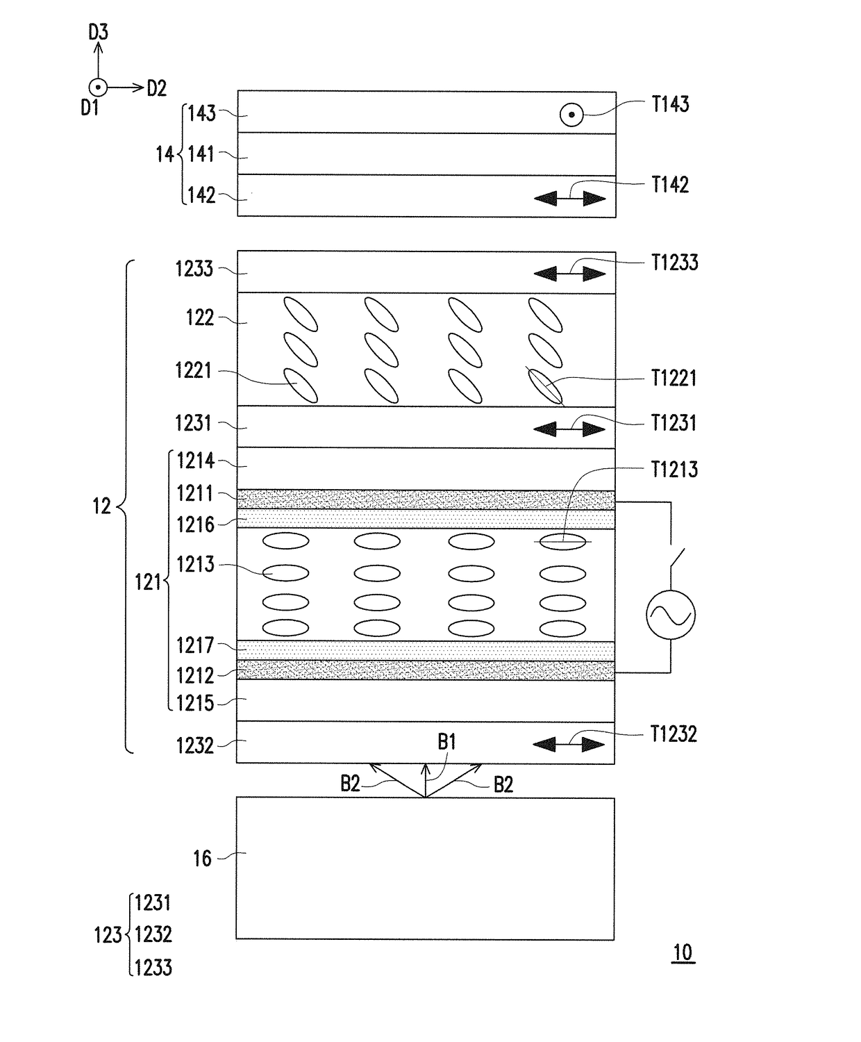
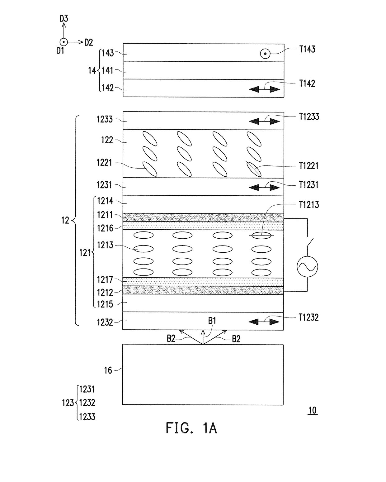
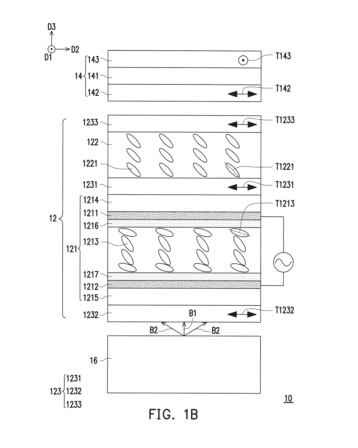
[0028]FIGS. 1A and 1B are sectional schematic views respectively illustrating a viewing angle controllable display apparatus in a general display mode and a privacy protecting mode according to the invention. FIGS. 1C and 1D are sectional schematic views respectively illustrating a first and a second light source modules in FIGS. 1A and 1B. Referring to FIGS. 1A and 1B, a viewing angle controllable display apparatus 10 includes a viewing angle control device 12 and a display panel 14.

[0029]The viewing angle control device 12 includes at least one liquid crystal panel 121, at least one compensation film 122 and a plurality of polarizers (the set of the plurality of polarizers is denoted by a numeral 123). Each of the at least one liquid crystal panel 121 includes a transparent conductive layer 1211, a transparent conductive layer 1212 and a plurality of liquid crystal molecules 1213 located between the transparent conductive layer 1211 and the transparent conductive layer 1212. In th...

third embodiment

[0058]FIG. 12 is a sectional schematic view illustrating a viewing angle controllable display apparatus in the general display mode according to the invention. Please refer to the descriptions concerning FIG. 1B for the details of privacy protecting mode of the viewing angle controllable display apparatus in FIG. 12, which will not be repeated therein.

[0059]Referring to FIG. 12, a viewing angle controllable display apparatus 30 is similar to the viewing angle controllable display apparatus 10 in FIG. 1A, wherein identical elements are denoted by the same reference numerals, which will not be repeated therein. The main difference between the viewing angle controllable display apparatus 30 and the viewing angle controllable display apparatus 10 is described below. In the viewing angle controllable display apparatus 30, an amount of the at least one compensation film 122 is two. The two compensation films 122 are, for example, the O-plate (the optical axis T1221 of the liquid crystal p...


PUM


Abstract

A viewing angle control device including at least one liquid crystal panel, at least one compensation film and polarizers is provided. Each of the at least one liquid crystal panel includes two transparent conductive layers and liquid crystal molecules. The polarizers include at least one first polarizer and a second polarizer. The at least one first polarizer is located between the at least one compensation film and the at least one liquid crystal panel. The second polarizer is located at a side of the at least one liquid crystal panel, the at least one compensation film and the at least one first polarizer. When there is no potential difference between the transparent conductive layers, an optical axis of each of the liquid crystal molecules is parallel or vertical to a transmission axis of the at least one first polarizer. A viewing angle controllable display apparatus is also provided.

Description

CROSS-REFERENCE TO RELATED APPLICATION[0001]This application claims the priority benefit of Taiwan application serial no. 105216211, filed on Oct. 25, 2016. The entirety of the above-mentioned patent application is hereby incorporated by reference herein and made a part of this specification.BACKGROUND OF THE INVENTIONField of the Invention[0002]The invention relates to an optical device and a display device using the optical device, and more particularly to a viewing angle control device and a viewing angle controllable display apparatus using the viewing angle control device.Description of Related Art[0003]Generally speaking, in order for more viewers to be able to see, a display device is usually designed to have a wide viewing angle for better display effect. However, under some particular circumstances or on special occasions, e.g. browsing a personal web page, confidential information or inputting password at a public space, the display effect of wide viewing angle can easily ...

Claims


Application Information

Patent Timeline
IPC IPC(8): G02F1/13G02F1/13363G02F1/1335
CPCG02F1/1323G02F1/13363G02F1/133528G02F2001/133531G02F2001/133638G02F2413/02G02B6/0055G02B6/0051G02B6/0053G02F2413/05G02F2001/133633G02F1/133632G02F1/133634G02F1/13471G02F2413/10G02F1/133633G02F1/133531G02F1/133638
Inventor FANG, CHONG-YANGWANG, WEN-CHUN
Owner CORETRONIC
Why Eureka
Try Eureka