Interpolated tomosynthesis projection images

a technology of projection images and tomography, applied in the field of tomography, can solve the problems of reducing the intensity of artifacts and the limitation of the technique to producing synthetic mammography images at the positions

Active Publication Date: 2018-04-26
GENERAL ELECTRIC CO
View PDF2 Cites 10 Cited by
  • Summary
  • Abstract
  • Description
  • Claims
  • Application Information

AI Technical Summary

Problems solved by technology

However, the intensity of the artifact diminishes with each additional projection image used in the reconstruction.
However, those techniques are limited to producing synthetic mammography images at the positions from which the original tomosynthesis projection images were acquired.

Method used


Image

  • Interpolated tomosynthesis projection images
  • Interpolated tomosynthesis projection images
  • Interpolated tomosynthesis projection images

Examples


Embodiment Construction

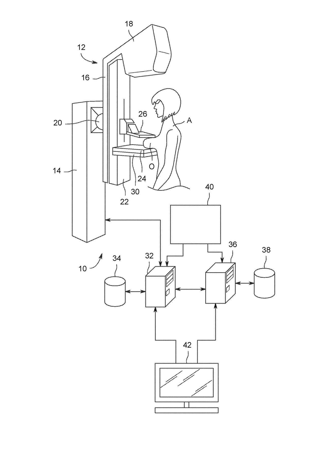
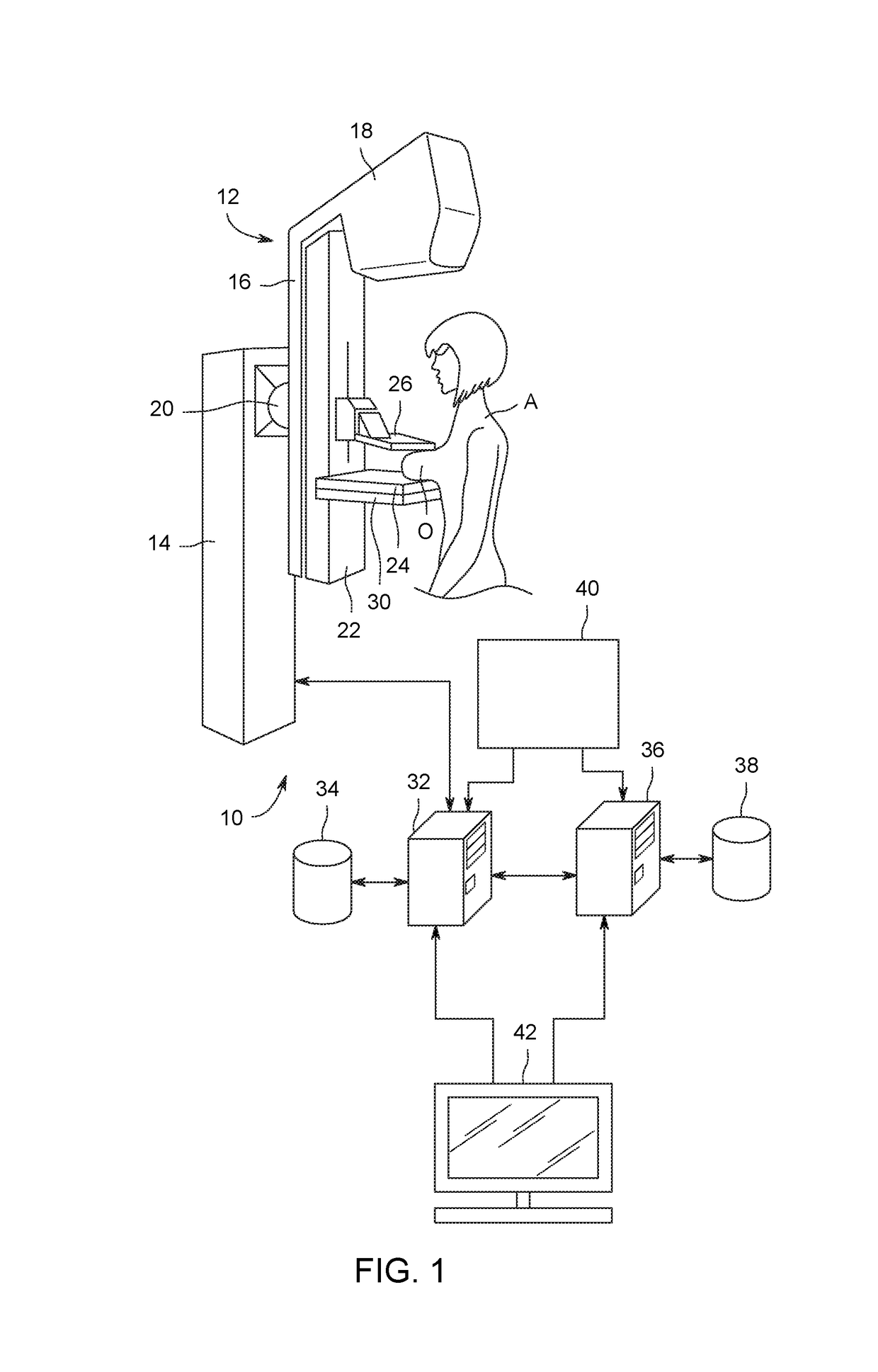
[0018]FIG. 1 depicts an exemplary embodiment of a medical imaging system 10. The medical imaging system 10 exemplarily operates in the manners as described herein in order to create synthetic projection images which may be used to create improved three-dimensional reconstruction images and synthetic two-dimensional images. The medical imaging system 10, as described in further detail herein enables the acquisition of 2D projection images of a tissue matrix of an organ O, exemplarily a breast of a patient A. The medical imaging system 10 processes the 2D projection images as described in further detail herein to create a 3D reconstruction of the tissue matrix of the organ O.

[0019]The imaging system 10 includes an acquisition unit 12 which operates to acquire the 2D projection images. The acquisition unit 12 exemplarily includes a vertical stand 14 and a positioning arm 16 which includes a radiation source 18 e.g. an X-ray emitter. The positioning arm 16 is exemplarily rotationally jo...


PUM


Abstract

Systems and methods of medical imaging includes acquiring a plurality of projection images. A first projection image and a second projection image from the plurality of projection images are selected that are adjacent to a received focal point. A first set of object locations in the first projection image and a second set of object locations in the second projection image are identified that contribute to a pixel of the synthetic projection image. A value for the pixel of the synthetic projection image is calculated from the pixels of the first set of object locations and the pixels of the second set of object locations. The synthetic projection image is created with the calculated value.

Description

BACKGROUND[0001]The present disclosure is related to the field of tomography. More specifically, the present disclosure is related to the field of digital breast tomography (DBT), the interpolation of synthetic projection images from DBT data, and the use of such synthetic projection images.[0002]For the diagnosis of breast cancer, radiology is generally used to obtain an image of the inside of the breast. A two-dimensional (2D) radiological image shows a projection of a tissue matrix, e.g. a breast for breast cancer diagnosis, onto a plane formed by a detector, from a radiation source. The radiological image is generally obtained by placing the object of interest between the X-ray emitting source and the X-ray detector, so that the rays reach the detector after passing through the object. The radiological image is then created from data provided by the detector, and represents the tissue matrix projected onto the detector in the direction of the X-rays.[0003]In such a radiological ...

Claims


Application Information

Patent Timeline
Patent Type & Authority Applications(United States)
IPC IPC(8): G06T7/00G06T11/00G06T15/08A61B6/00A61B6/02
CPCG06T7/0012G06T7/0042G06T11/003G06T2207/10116A61B6/502A61B6/466A61B6/025G06T15/08G06T2211/436G06T11/005G06T11/006G06T7/73
Inventor PALMA, GIOVANNI JOHN JACQUES
Owner GENERAL ELECTRIC CO
Why Eureka
Try Eureka