Forced zero voltage switching flyback converter

a converter and zero-voltage technology, applied in the field of isolated power converters, can solve the problems of undesirable variable frequency operation and power loss of flyback converters

Active Publication Date: 2018-04-26
ALPHA & OMEGA SEMICON INC
View PDF2 Cites 31 Cited by
  • Summary
  • Abstract
  • Description
  • Claims
  • Application Information

AI Technical Summary

Problems solved by technology

Flyback converters suffer from power losses when switching transitions occur with non-zero voltages across the power switches.
Variable frequency operation is undesirable, especially when avoidance of electromagnetic interference (EMI) disturbance is important.

Method used


Image

  • Forced zero voltage switching flyback converter
  • Forced zero voltage switching flyback converter
  • Forced zero voltage switching flyback converter

Examples


Embodiment Construction

[0017]The invention can be implemented in numerous ways, including as a process; an apparatus; a system; and / or a composition of matter. In this specification, these implementations, or any other form that the invention may take, may be referred to as techniques. In general, the order of the steps of disclosed processes may be altered within the scope of the invention.

[0018]A detailed description of one or more embodiments of the invention is provided below along with accompanying figures that illustrate the principles of the invention. The invention is described in connection with such embodiments, but the invention is not limited to any embodiment. The scope of the invention is limited only by the claims and the invention encompasses numerous alternatives, modifications and equivalents. Numerous specific details are set forth in the following description in order to provide a thorough understanding of the invention. These details are provided for the purpose of example and the inv...


PUM


Abstract

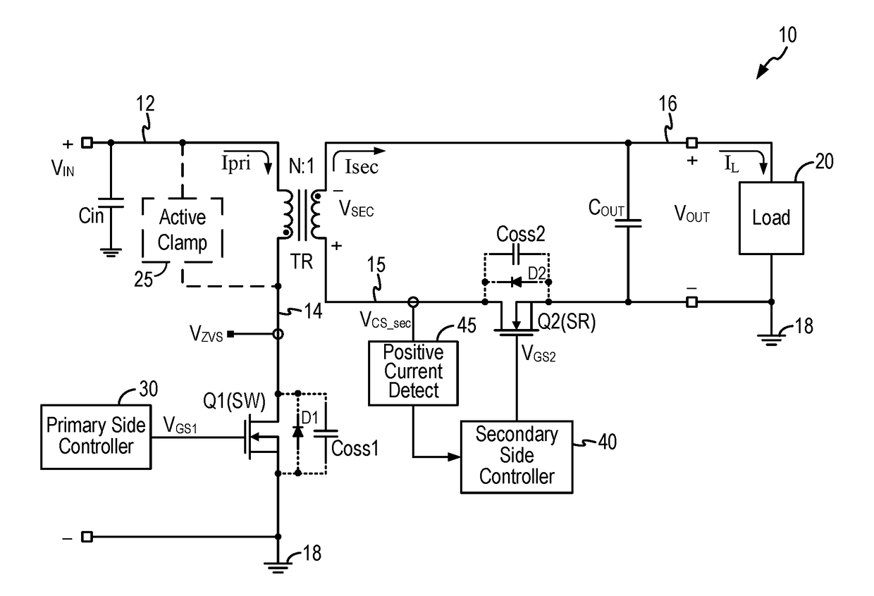
A flyback converter implements a Forced Zero Voltage Switching (ZVS) timing control by detecting a positive current excursion of the secondary winding current as the synchronous rectifier turn off trigger. The synchronous rectifier switch is turned on near the end of the switching cycle or the on duration is extended to develop a current ripple on the secondary winding current. The control circuit of the flyback converter detects a positive current excursion on the secondary winding current to turn off the synchronous rectifier and to start the next switching cycle. At this point, the voltage across the primary switch has been discharged and the primary switch can be turned on with zero drain-to-source voltage. In other embodiments, zero voltage switching for the off-transition of the primary switch is realized by coupling a capacitor across the primary switch or by coupling a capacitor across the primary winding, or both.

Description

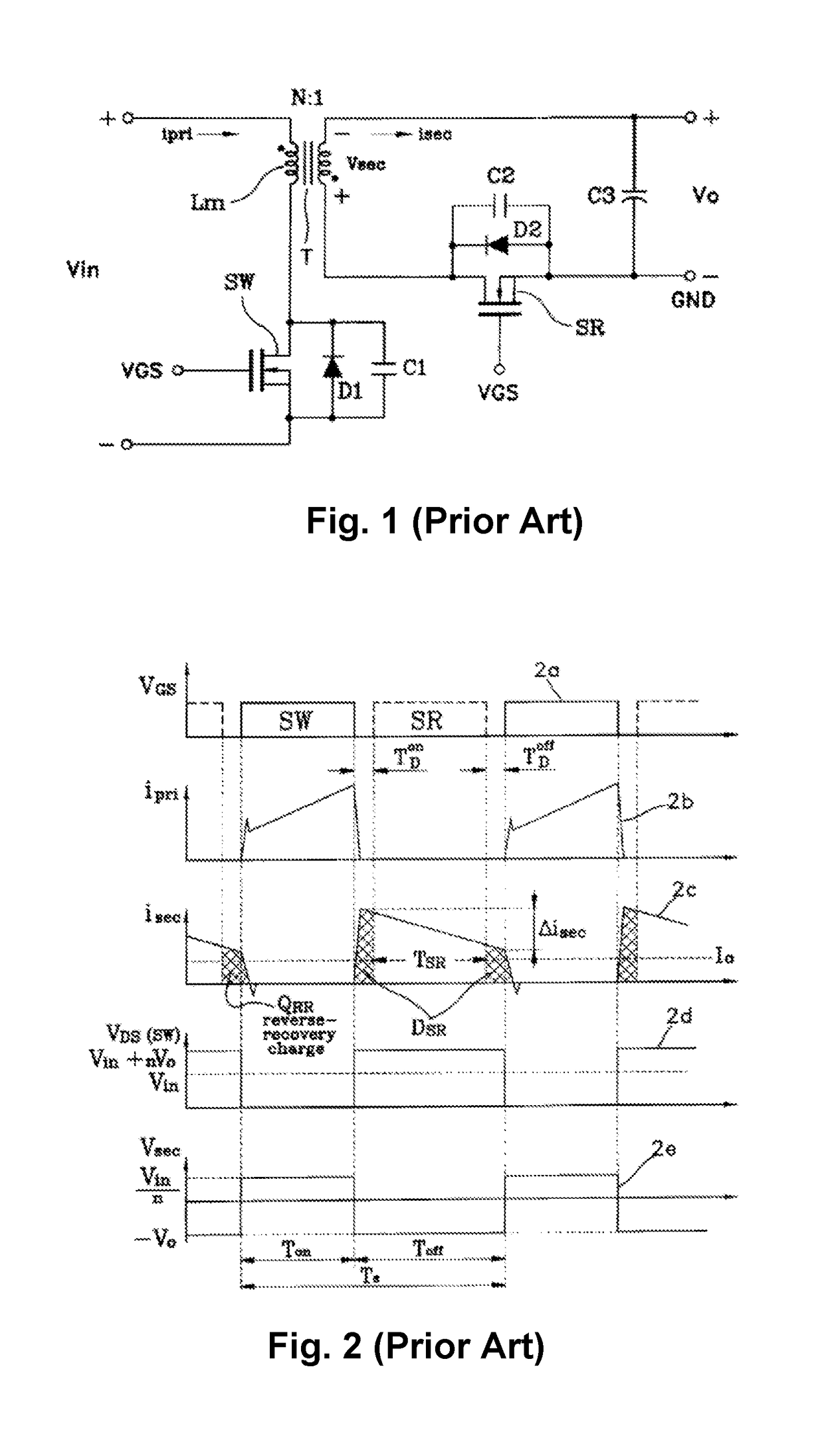
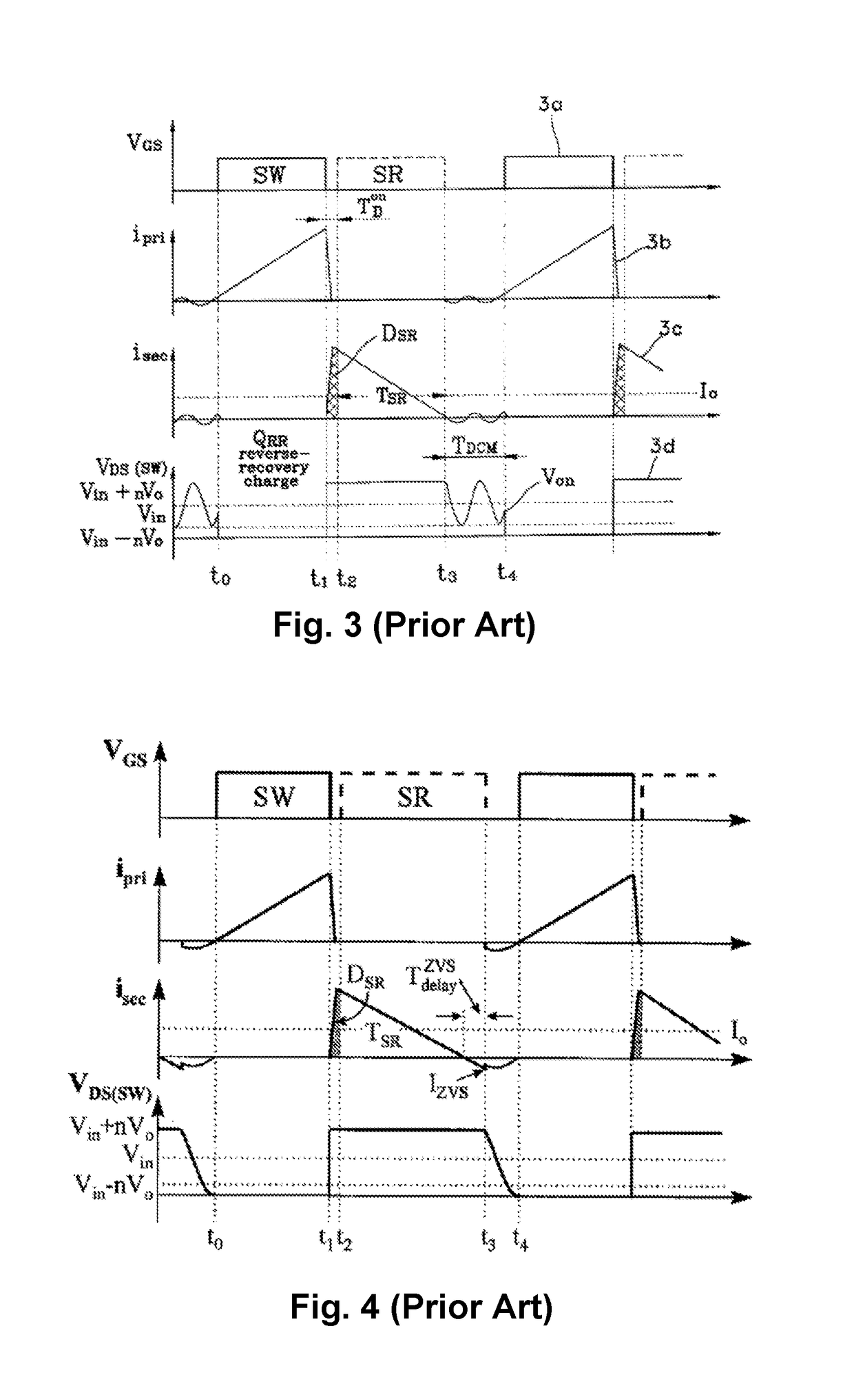
BACKGROUND OF THE INVENTION[0001]The flyback converter is an isolated power converter that is commonly used in both AC-to-DC and DC-to-DC conversion with galvanic isolation between the input and the one or more outputs. More specifically, the flyback converter is a buck-boost converter with the inductor split to form a transformer, so that the voltage ratios are multiplied with an additional advantage of isolation. Synchronous rectification is often applied to replace the diode rectifier to improve efficiency. FIG. 1 is an example of a flyback converter using synchronous rectification. As shown in FIG. 1, a typical construction of the flyback converter includes a primary switch (SW) coupled to the primary transformer winding of a transformer Lm and a synchronous rectifier switch (SR) coupled to the secondary transformer winding of the transformer Lm. The input voltage VIN is provided across the primary winding and the primary switch. The primary switch is controlled by a control vol...

Claims


Application Information

Patent Timeline
Patent Type & Authority Applications(United States)
IPC IPC(8): H02M3/335H02M1/08H02M1/32
CPCH02M3/33592H02M1/08H02M1/32H02M1/083H02M2007/4815H02M1/047H02M2001/0058H02M2001/0009H02M1/14H02M1/44H02M3/33523H02M1/0048Y02B70/10H02M1/0009H02M1/0058H02M7/4815
Inventor CHANG, KUANG MINGCHEN, LINHUANG, QIHONG
Owner ALPHA & OMEGA SEMICON INC
Why Eureka
Try Eureka