
Insect control lighting device

a technology for insects and lighting devices, applied in the field of insect control, can solve the problems of insufficient attraction and elimination of insects, death of thirst, hunger, or age, and difficulty in handling fly paper,

Active Publication Date: 2018-05-03
CLEAN CONCEPT LLC
View PDF72 Cites 3 Cited by
  • Summary
  • Abstract
  • Description
  • Claims
  • Application Information

AI Technical Summary

Benefits of technology

The present invention is about improving devices used for controlling insects. It describes a lighting device that can attract or repel insects using different spectra of light. The device has a housing and an inner module that can be inserted into the housing. The inner module contains insect control material, like attractants or repellants, and can be easily replaced when the material is no longer effective or when the insect control is needed in a different location. This invention allows for easy and flexible control of insects in various settings.

Problems solved by technology

Because insects cannot separate themselves from the paper, they ultimately die of thirst, hunger, or age.
Handling fly paper, however, may be difficult because the adhesive is typically very strong and may inadvertently attach itself to the person installing the fly paper.
However, placing the fly paper in a remote location may not adequately attract and eradicate insects.
However, candles are a potential fire hazard and often produce unwanted smoke and wax drippings.
Many flying insects, including mosquitos are drawn to lights, and insects are electrocuted when they make contact with the charged elements.
Some bug zappers need to be placed on the floor or another flat surface and may be accidentally contacted by persons or pets passing near the bug zapper.
However, mounting the bug zappers can be difficult and / or time consuming.
Also, bug zappers typically need to be plugged into an electric socket, further complicating installation.
However, the active ingredient dispenser is contained within the base and is not placed in proximity to the light sources and / or used with an adhesive chemical to eradicate insects.

Method used


Image

  • Insect control lighting device
  • Insect control lighting device
  • Insect control lighting device

Examples


Embodiment Construction

[0022]The invention may be understood more readily by reference to the following detailed description of a preferred embodiment of the invention. However, techniques, systems, and operating structures in accordance with the invention may be embodied in a wide variety of forms and modes, some of which may be quite different from those in the disclosed embodiment. Consequently, the specific structural and functional details disclosed herein are merely representative, yet in that regard, they are deemed to afford the best embodiment for purposes of disclosure and to provide a basis for the claims herein, which define the scope of the invention. It must be noted that, as used in the specification and the appended claims, the singular forms “a”, “an”, and “the” include plural referents unless the context clearly indicates otherwise.

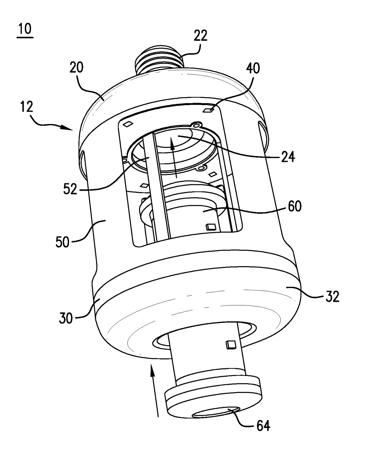
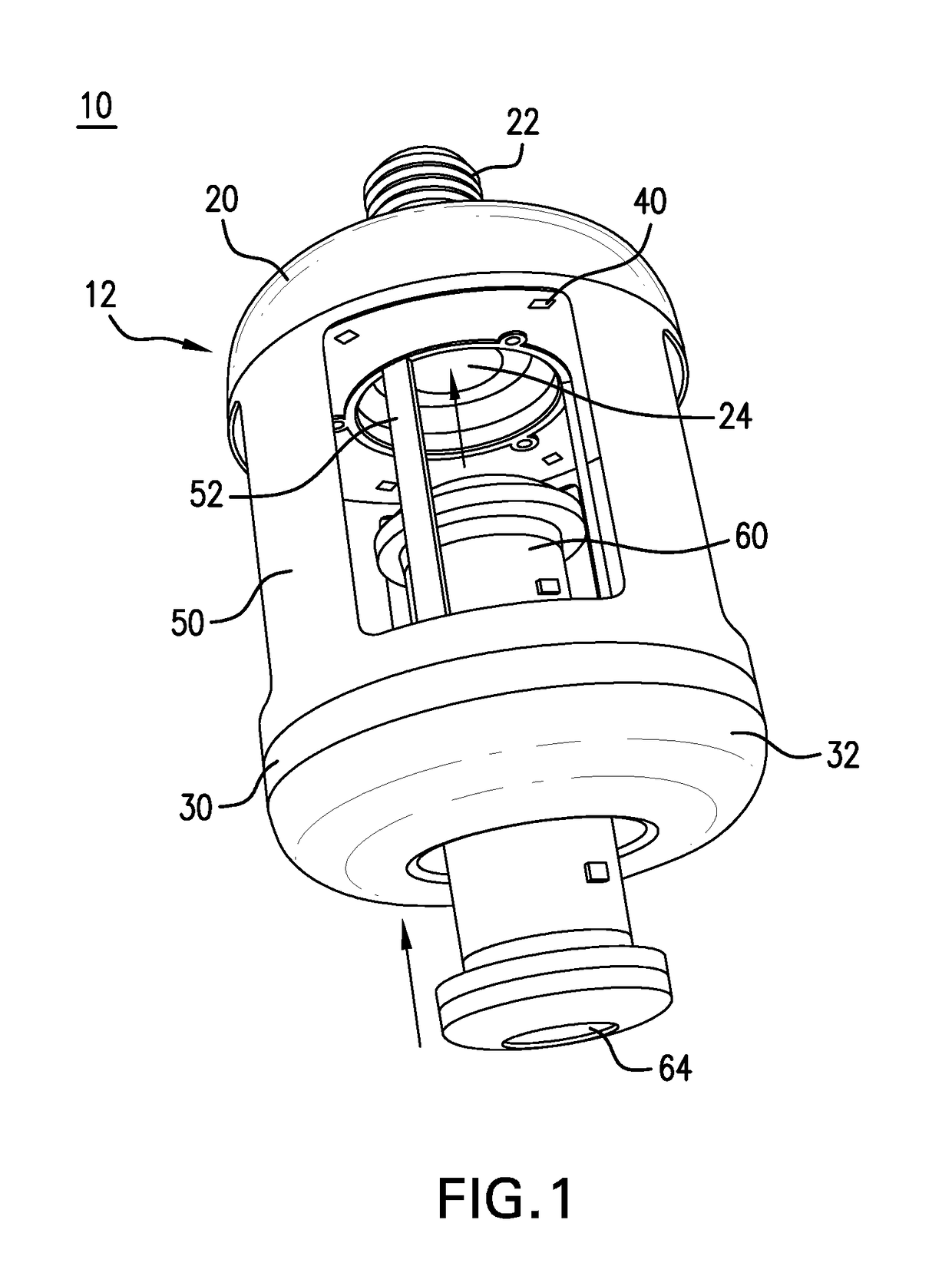
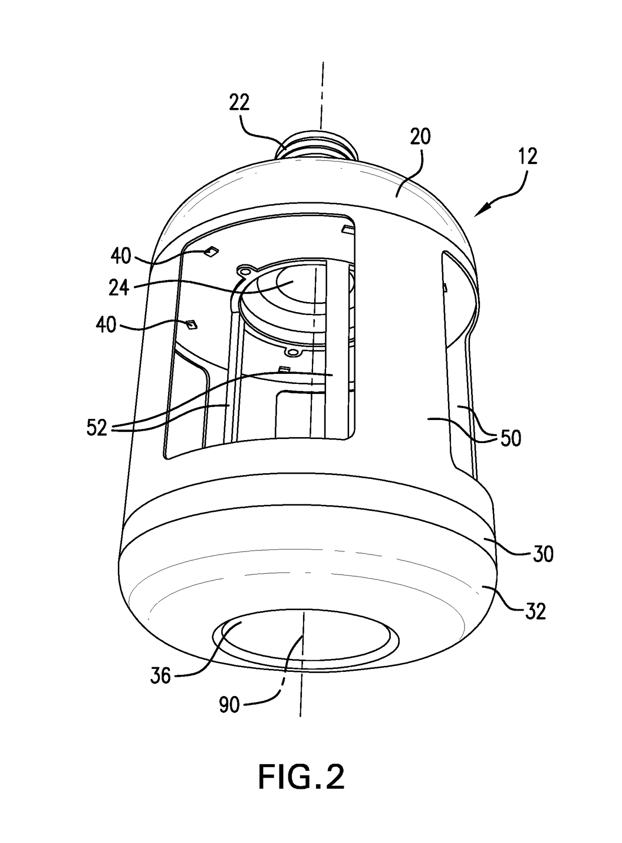
[0023]Referring to FIG. 1, there is shown an embodiment of an insect control lighting device (10) in accordance with the present invention. Lighting device (1...


PUM


Abstract

An insect control lighting device having a connector capable of electrically connecting to a common lightbulb socket or electrical outlet. The lighting device includes one or more light sources in electrical connection with the connector. The lighting device further includes an inner module having one or more insect control materials, such an insect attractant and an adhesive. The inner module may be secured within the lighting device by a magnet or by screw threads at one or both ends of the inner module.

Description

CROSS-REFERENCE TO RELATED APPLICATIONS[0001]This application claims the benefit of U.S. Provisional Patent Application No. 62 / 415,153, filed Oct. 31, 2016. The entire contents of that application are incorporated herein by reference.FIELD OF THE INVENTION[0002]This invention relates to the field of insect control and, more particularly, to a lighting device with an inner insect control module.BACKGROUND OF THE INVENTION[0003]Various means exist for controlling insects in or around the home. For example, adhesive strips, sometimes referred to as “fly paper” may be used to attract and eradicate insects. Insects may be attracted to an insect attractant applied to the paper, and when the insects land on the paper, an adhesive ensures that the insects remains stuck to the paper. Because insects cannot separate themselves from the paper, they ultimately die of thirst, hunger, or age. Handling fly paper, however, may be difficult because the adhesive is typically very strong and may inadv...

Claims


Application Information

Patent Timeline
IPC IPC(8): A01M1/14A01M1/02A01M29/10A01M1/10F21V23/06F21V23/00
CPCA01M1/145A01M1/02F21Y2115/10F21V23/06F21V23/004A01M1/106A01M1/04A01M1/22F21V17/10F21V23/00H05B47/10A01M29/12A01M1/023F21K9/23
Inventor VAN KLEEF, PAUL
Owner CLEAN CONCEPT LLC
Learn More