
Vehicle control device

a technology for controlling devices and vehicles, applied in control devices, external condition input parameters, vehicle components, etc., can solve problems such as decreased grip force, and increased braking distance of vehicles

Active Publication Date: 2018-05-03
DENSO CORP +1
View PDF4 Cites 24 Cited by
  • Summary
  • Abstract
  • Description
  • Claims
  • Application Information

AI Technical Summary

Benefits of technology

The present patent discloses a vehicle control device that can appropriately control acceleration and deceleration of a vehicle taking into account variation of the friction coefficient between each tire and the road surface. This is achieved by attaching a vibration detection unit to a back side of a tire fitted to a tire wheel mounted on a vehicle and transmitting the detection signal to a signal processing unit on a tire-side device, which generates μ data representing the friction coefficient between the tire and the road surface. The μ data is then received by a vehicle-side device and used to estimate the braking distance of the vehicle using a friction coefficient estimation unit. Based on the braking distance, the acceleration and deceleration of the vehicle is controlled using an acceleration deceleration control unit. This enables adjustment of timing of vehicle acceleration and deceleration according to the braking distance estimated based on the friction coefficient. Overall, this vehicle control device ensures safer and efficient vehicle control in various road conditions.

Problems solved by technology

However, when the friction coefficient μ between each tire and the road surface is low, for example, when a vehicle is traveling on a low-μ road with a low road surface μ like a snow-covered road or a frozen road or when the tire is worn, the grip force decreases and the braking distance of the vehicle increases.
The braking distance of the vehicle can increase also when the tire pressure is low and when the ground contact load of each tire wheel of the vehicle is excessively large.
In such cases, it may not be possible to appropriately control acceleration and deceleration of the vehicle based on the assumption that the friction coefficient μ between each tire of the vehicle and the road surface is high.
For example, it may not be possible to maintain an appropriate inter-vehicle distance using an ACC system or a collision mitigation brake system.

Method used


Image

  • Vehicle control device
  • Vehicle control device
  • Vehicle control device

Examples


first embodiment

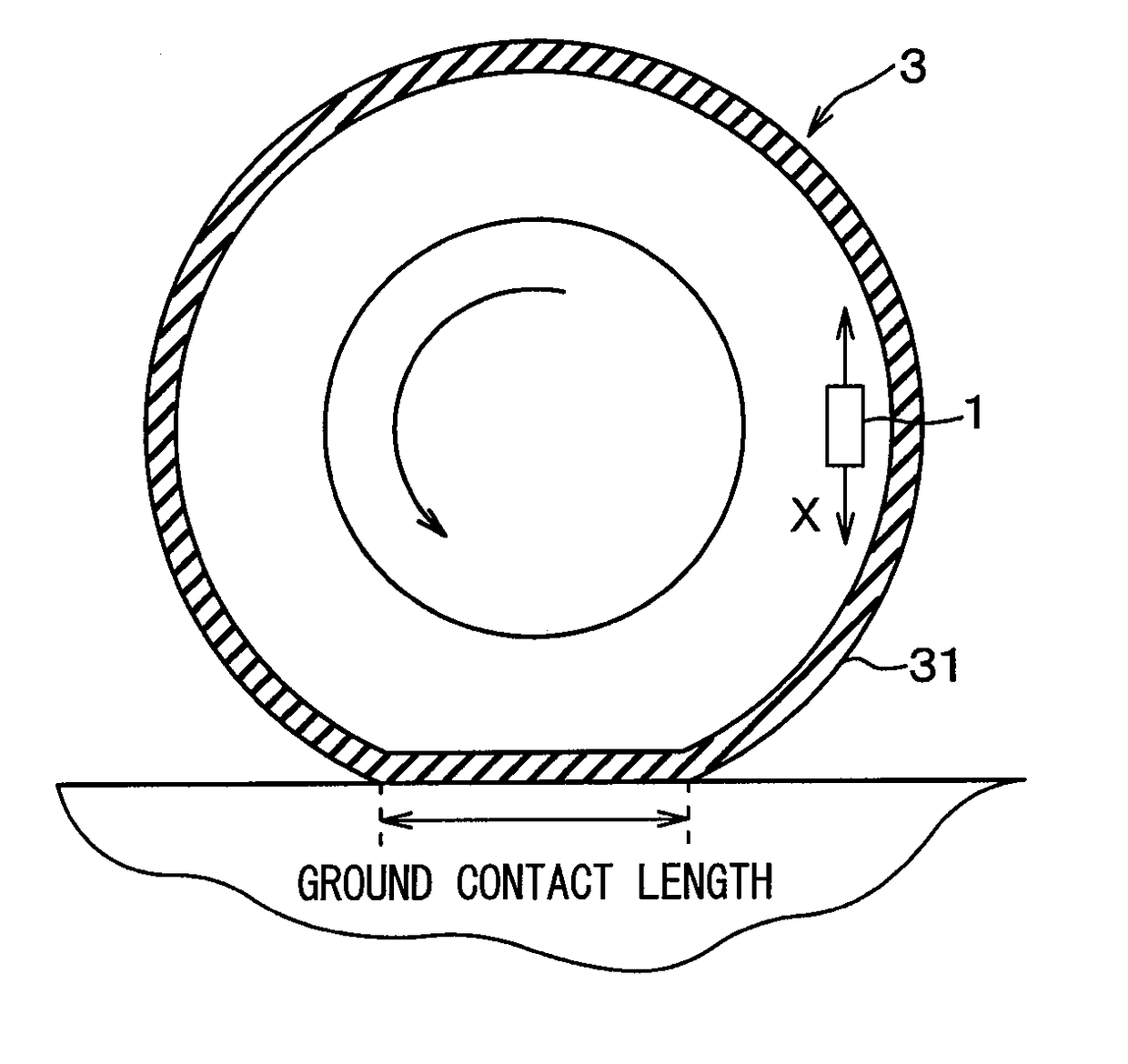
[0021]Referring to FIGS. 1 to 5, a vehicle control device 100 of the present embodiment will be described. The vehicle control device 100 of the present embodiment is used to estimate the surface condition of a road on which a vehicle is traveling based on the vibration of the contact area of the tire fitted on each tire wheel of the vehicle and to control acceleration deceleration of the vehicle based on the estimation results.

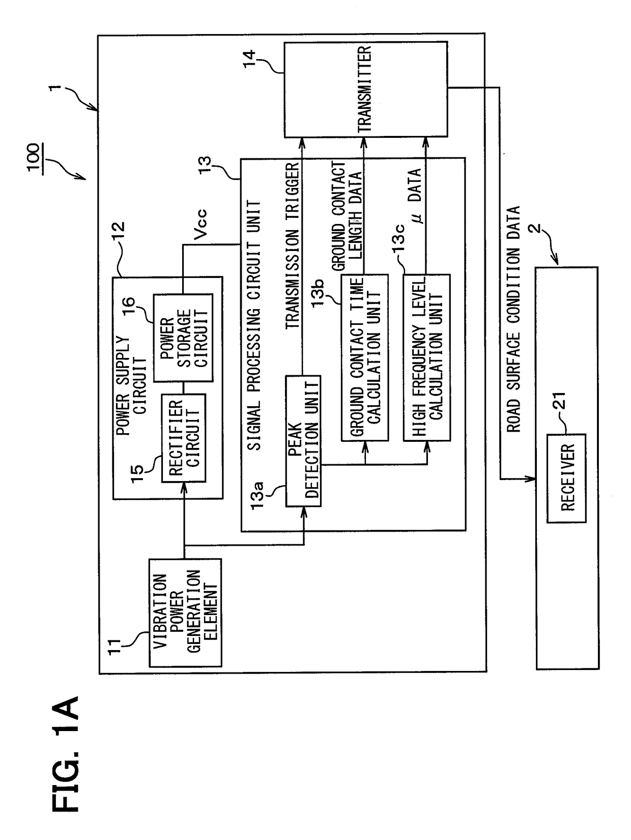
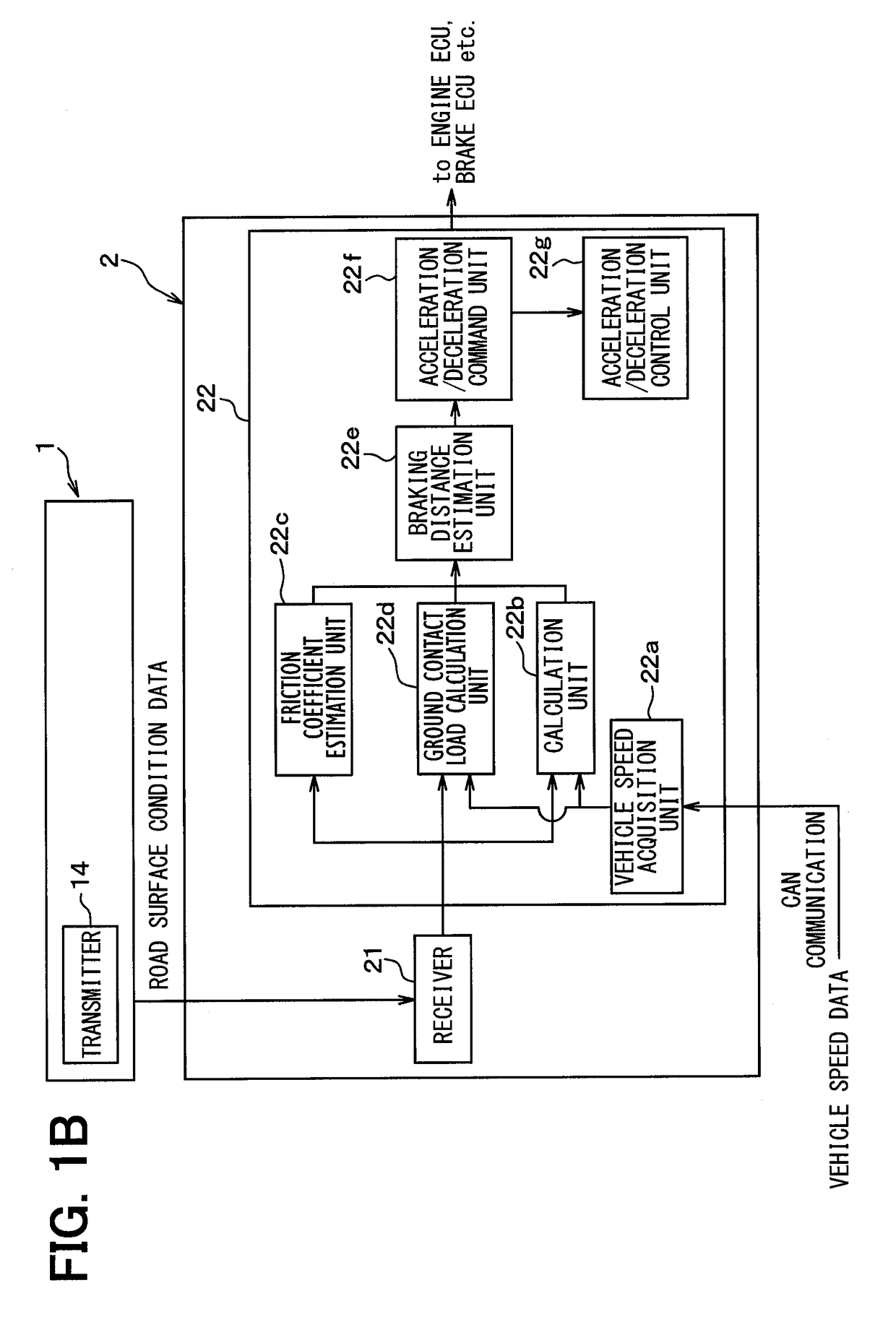
[0022]As shown in FIGS. 1A and 1B, the vehicle control device 100 is configured including a tire-side device 1 provided on the tire side and a vehicle-side device 2 provided on the vehicle body side. The vehicle control device 100 transmits, from the tire-side device 1, data (hereinafter referred to as “μ data”) representing friction coefficient μ between the tire and the road surface on which the vehicle is traveling and data (hereinafter referred to as “ground contact length data”) about the ground contact time corresponding to the ground contact length of ...


PUM


Abstract

A vehicle control device including a tire-side device and a vehicle-side device is provided. The tire-side device includes a vibration detection unit that outputs a detection signal corresponding to a magnitude of vibration of a tire, a signal processing unit that generates μ data representing a friction coefficient between the tire and a road surface by processing the detection signal, and a transmitter that transmits the μ data. The vehicle-side device includes a receiver that receives the μ data and a travel control unit that estimates the friction coefficient based on the μ data, acquires a braking distance of the vehicle based on the friction coefficient, and controls acceleration and deceleration of the vehicle based on the braking distance.

Description

CROSS REFERENCE TO RELATED APPLICATION[0001]This application is based on Japanese Patent Application No. 2014-251943 filed on Dec. 12, 2014, the disclosure of which is incorporated herein by reference.TECHNICAL FIELD[0002]This disclosure relates to a vehicle control device that controls acceleration and deceleration of a vehicle so as to avoid collision with a preceding vehicle.BACKGROUND ART[0003]Adaptive cruise control (hereinafter referred to as “ACC”) and collision mitigation brake systems (for example, a pre-crash safety system (PCS: registered trademark)) are known which control acceleration and deceleration of a vehicle to avoid a collision with a preceding vehicle. In ACC, acceleration and deceleration of a vehicle are controlled by adjusting the distance between the vehicle and a preceding vehicle based on the traveling speed of the vehicle so as to avoid a collision with the preceding vehicle (see, for example, Patent Literature 1). A collision mitigation brake system comp...

Claims


Application Information

Patent Timeline
Patent Type & Authority Applications(United States)
IPC IPC(8): B60W30/16B60C19/00B60W30/14B60W40/068B60W40/13
CPCB60W30/16B60C19/00B60W30/143B60W40/068B60W40/13B60C2019/004B60W2400/00B60W2530/20B60W2550/148B60W2550/308B60W2520/10B60W2720/106B60W2710/0605B60W2710/18B60T8/1725B60T8/173B60T2210/12B60T7/22B60T8/17B60T2201/024B60C99/00B60W2420/10B60W2422/70B60W10/06B60W10/184B60W30/18109B60W2050/0057B60W2754/30B60T8/172B60W30/14B60W40/12B60W2552/40B60W2554/801
Inventor SUZUKI, YOUICHIROUTAKAOKA, AKIRAMORI, MASASHISEKIZAWA, TAKATOSHI
Owner DENSO CORP
Features
  • Generate Ideas
  • Intellectual Property
  • Life Sciences
  • Materials
  • Tech Scout
  • Unparalleled Data Quality
  • Higher Quality Content
  • 60% Fewer Hallucinations
Learn More