Tubular air cleaner

a technology of air cleaner and tube, which is applied in the direction of machine/engine, combustion-air/fuel-air treatment, and separation processes, etc., can solve the problems of increasing the pressure loss of air and disturbing the air flow, and achieve the effect of reducing the air pressure loss

Inactive Publication Date: 2018-05-03
TOYOTA BOSHOKU KK
View PDF5 Cites 7 Cited by
  • Summary
  • Abstract
  • Description
  • Claims
  • Application Information

AI Technical Summary

Benefits of technology

[0006]Accordingly, it is an objective of the present invention to provide a tubular air cleaner capable of reducing air pressure loss.

Problems solved by technology

Thus, the swirl flow of air strikes the back of the guide plate, which disturbs the air flow.
This increases the pressure loss of the air.

Method used


Image

  • Tubular air cleaner
  • Tubular air cleaner
  • Tubular air cleaner

Examples


Embodiment Construction

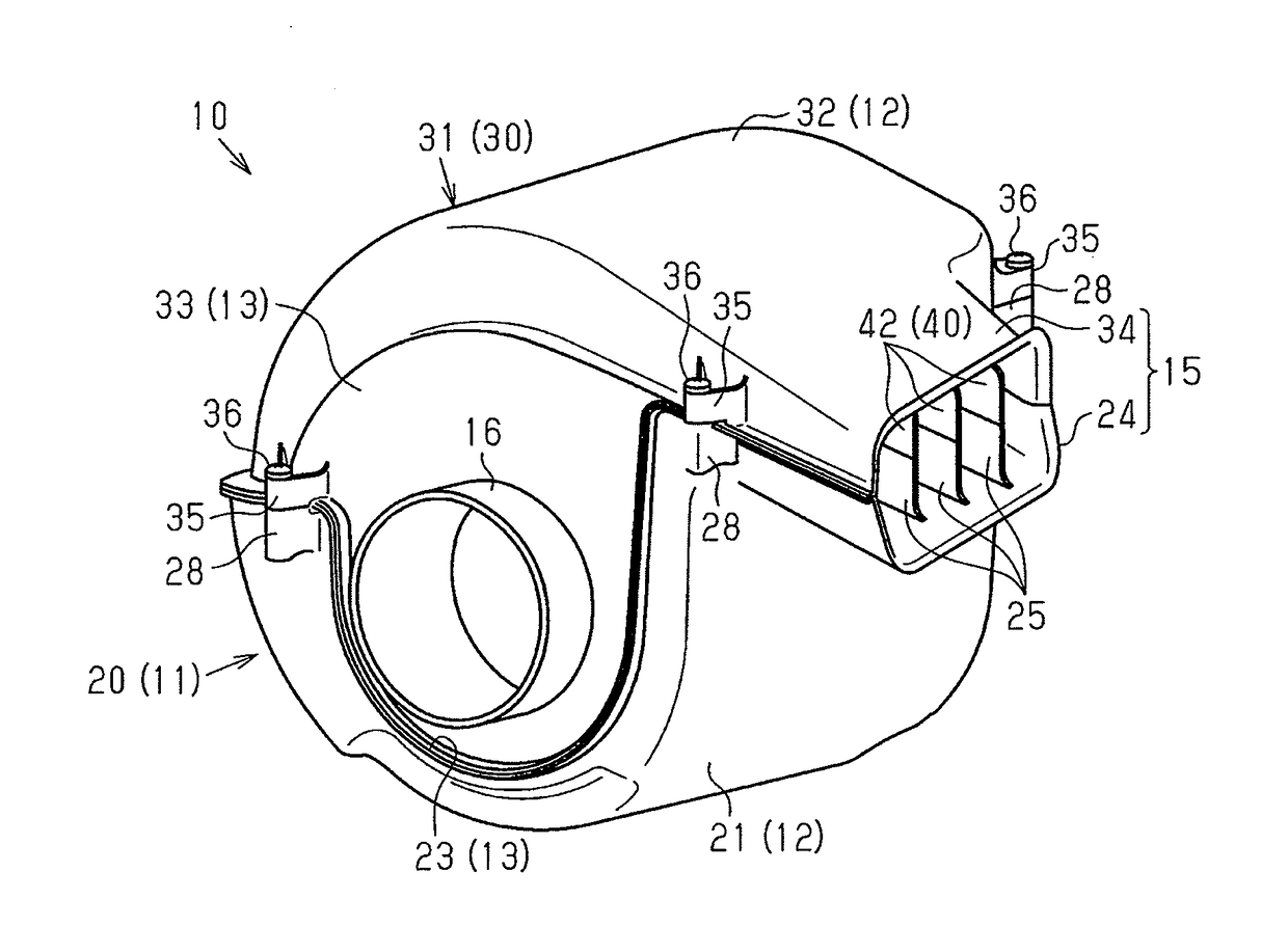
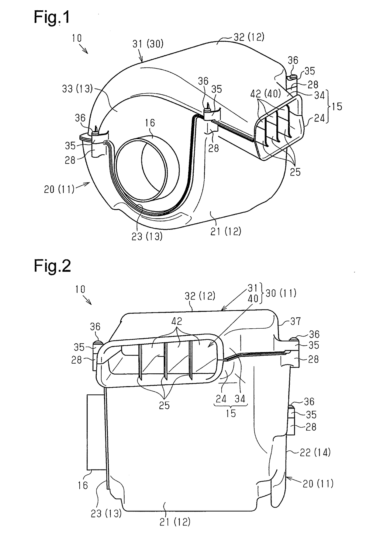
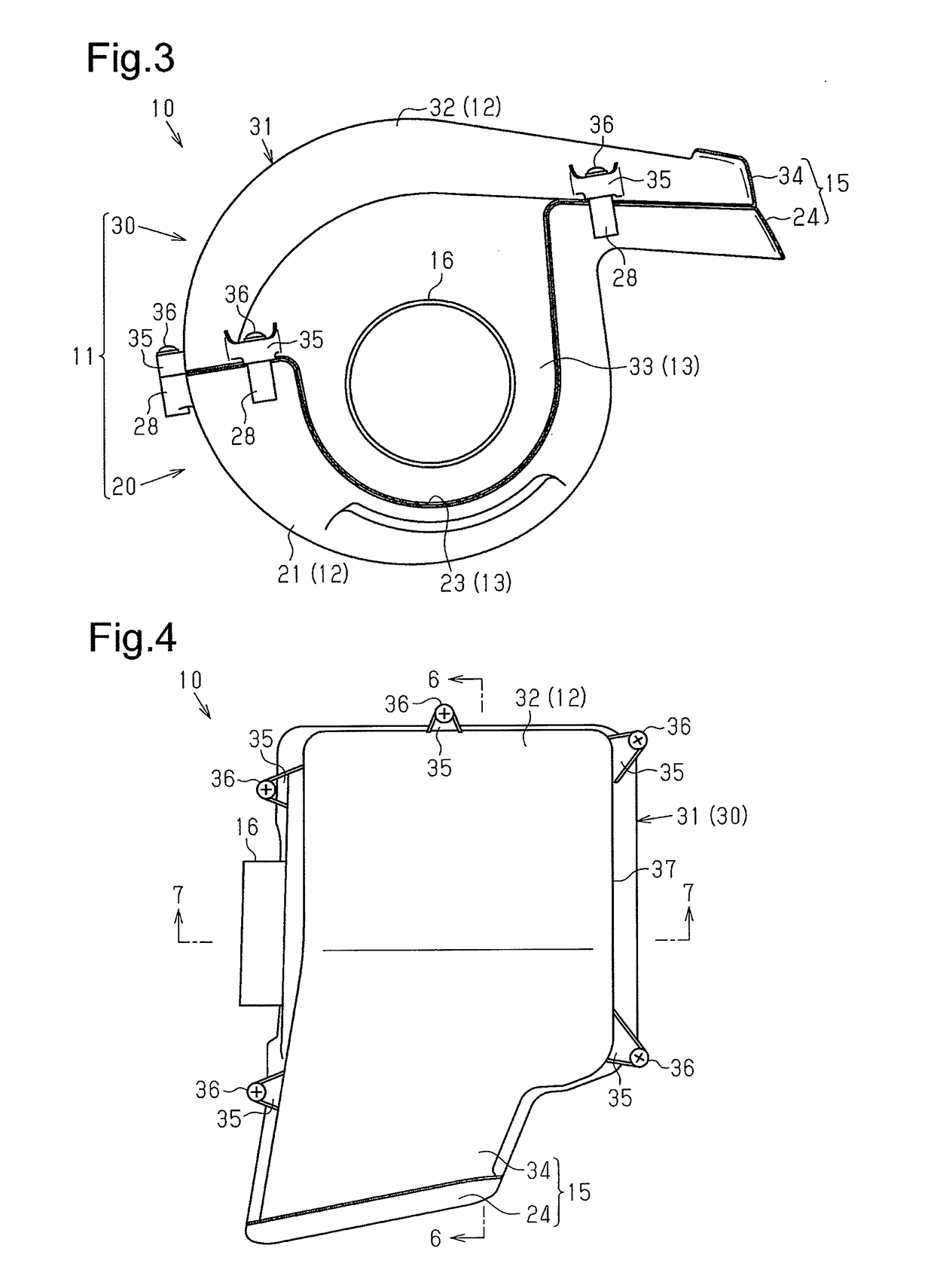
[0015]One embodiment will now be described with reference to FIGS. 1 to 7.

[0016]A tubular air cleaner (hereinafter referred to as an air cleaner 10) is provided in the intake passage of an in-vehicle internal combustion engine. As shown in FIGS. 1 to 7, the air cleaner 10 includes a cylindrical housing 11, which has a peripheral wall 12 and a bottom wall 13, and a multi-pointed star-shaped filter element 50, which is accommodated in the housing 11. An inlet 15 is formed in the peripheral wall 12. An outlet 16 is formed in the bottom wall 13.

[0017]As shown in FIG. 6, the filter element 50 is arranged eccentrically with respect to the axis of the housing 11.

[0018]The components of the air cleaner 10 will now be described.

[0019]50>

[0020]As shown in FIGS. 5 to 7, the filter element 50 has a filtration portion 51, which is formed by pleating a filtering medium sheet of, for example, nonwoven fabric or filter paper and then making a cylindrical shape with the pleated sheet. The end of the...


PUM

PropertyMeasurementUnit
circumferenceaaaaaaaaaa
distanceaaaaaaaaaa
cross-sectional areaaaaaaaaaaa

Abstract

A tubular air cleaner includes a housing, which has a peripheral wall and a bottom wall, an inlet, which is formed in the peripheral wall, an outlet, which is formed in the bottom wall, a filter element, and a partition wall portion. The filter element has a filtration portion and is accommodated in the housing. The partition wall portion forms the inlet together with the peripheral wall. The filter element is arranged eccentrically with respect to the axis of the housing. An air flow path is formed between the filtration portion and the inner peripheral surfaces of the peripheral wall and the partition wall portion. The air flow path has a gradual change portion, in which the distance between the inner peripheral surface of the peripheral wall and the outer peripheral surface of the filtration portion gradually decreases toward the downstream end.

Description

BACKGROUND OF THE INVENTION[0001]The present invention relates to a tubular air cleaner.[0002]Conventionally, a tubular air cleaner (hereinafter referred to as an air cleaner) has a cylindrical housing and a filter element accommodated in the housing. The filter element has a cylindrical structure with a multi-pointed star-shaped outer configuration (for example, Japanese Laid-Open Patent Publication No. 61-255258).[0003]The housing of the air cleaner described in the publication includes a peripheral wall, which has a cylindrical inlet projecting in a tangential direction of the peripheral wall. The housing also has a cylindrical outlet projecting from the bottom wall. The housing accommodates a guide plate for guiding the air flowing in through the inlet. The guide plate defines an air flow path such that the air flow path becomes closer to the periphery toward the downstream end and decreases the cross-sectional area of the air flow path toward the downstream end. Further, the gu...

Claims


Application Information

Patent Timeline
Patent Type & Authority Applications(United States)
IPC IPC(8): F02M35/024F02M35/02F02M35/022
CPCF02M35/02416F02M35/0216F02M35/0223F02M35/02483B01D46/0036B01D46/0045B01D46/0046B01D46/2411B01D46/521B01D50/20
Inventor ISHIZUKA, SATOSHIMARUYAMA, KAZUSHIGE
Owner TOYOTA BOSHOKU KK
Why Eureka
Try Eureka