Cylindrical air cleaner for internal combustion engine

a technology of internal combustion engine and air cleaner, which is applied in the direction of machines/engines, combustion-air/fuel-air treatment, and separation processes, etc., can solve the problems of increasing airflow resistance, and achieve the effect of reducing air pressure loss and increasing airflow resistan

Active Publication Date: 2020-03-17
TOYOTA BOSHOKU KK
View PDF20 Cites 0 Cited by
  • Summary
  • Abstract
  • Description
  • Claims
  • Application Information

AI Technical Summary

Benefits of technology

[0005]The filter element described in Japanese Laid-Open Patent Publication No. 2001-123897 has the drawback of increasing the airflow resistance. The reason is that although the inner tube has a number of air holes, the inner tube blocks a passage through which the air flows. Therefore, there is room for improvement to reduce the air pressure loss.
[0006]It is an object of the present invention to provide a cylindrical air cleaner for an internal combustion engine that reduces air pressure loss.

Problems solved by technology

The filter element described in Japanese Laid-Open Patent Publication No. 2001-123897 has the drawback of increasing the airflow resistance.

Method used


Image

  • Cylindrical air cleaner for internal combustion engine
  • Cylindrical air cleaner for internal combustion engine
  • Cylindrical air cleaner for internal combustion engine

Examples


first embodiment

[0016]A first embodiment will now be described with reference to FIGS. 1 to 5.

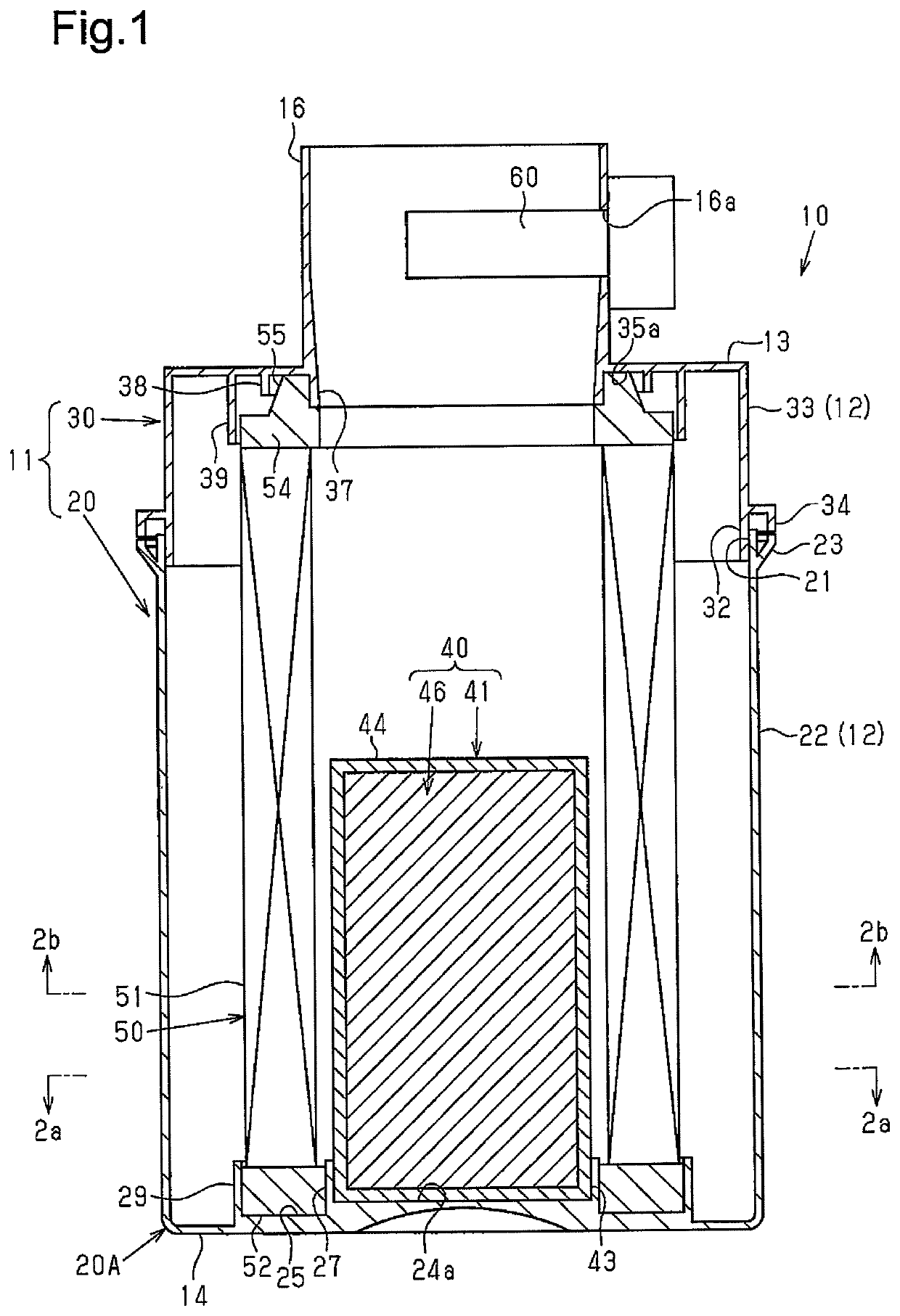
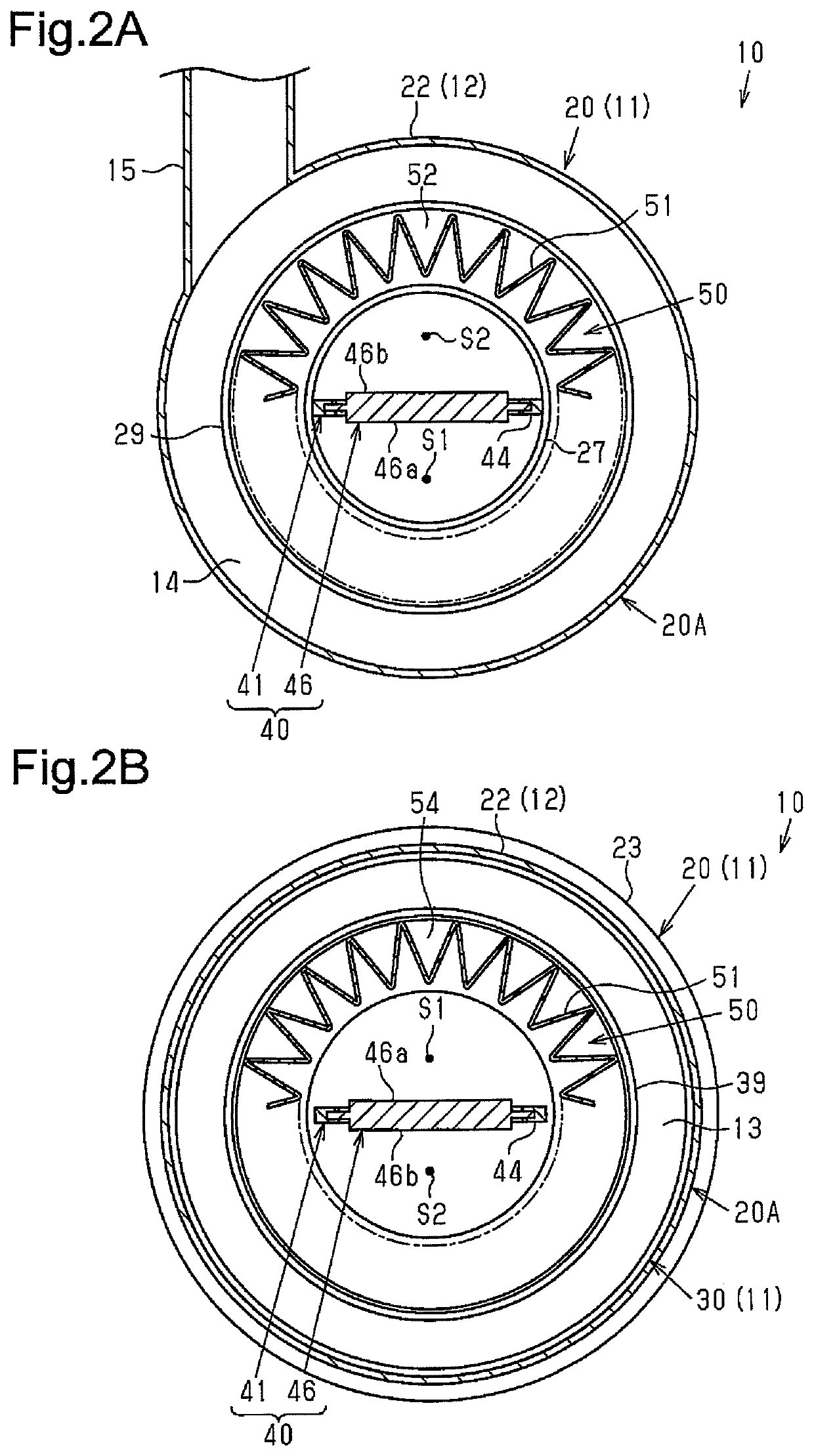
[0017]As shown in FIGS. 1, 2A, and 2B, a cylindrical air cleaner (hereafter, referred to as air cleaner 10), which is arranged in an intake air passage of an internal combustion engine, includes a cylindrical housing 11. The housing 11 includes a circumferential wall 12 having an inlet 15, a top wall 13 having an outlet 16, and a bottom wall 14 opposed to the top wall 13. A tubular filter element 50 is accommodated in the housing 11.

[0018]Filter Element 50

[0019]As shown in FIGS. 1, 2A, and 2B, the filter element 50 includes a pleated tubular filter portion 51, which is formed by pleating a filter medium sheet such as a non-woven fabric or filter paper, a first sealing portion 52, and a second sealing portion 54, each of which is disk-shaped and has a center hole. The first sealing portion 52 and the second sealing portion 54 are located on one end and another end of the filter portion 51 in an axial direct...

second embodiment

[0057]A second embodiment of an adsorbent filter assembly 40 will now be described focusing on the differences from the first embodiment with reference to FIG. 6.

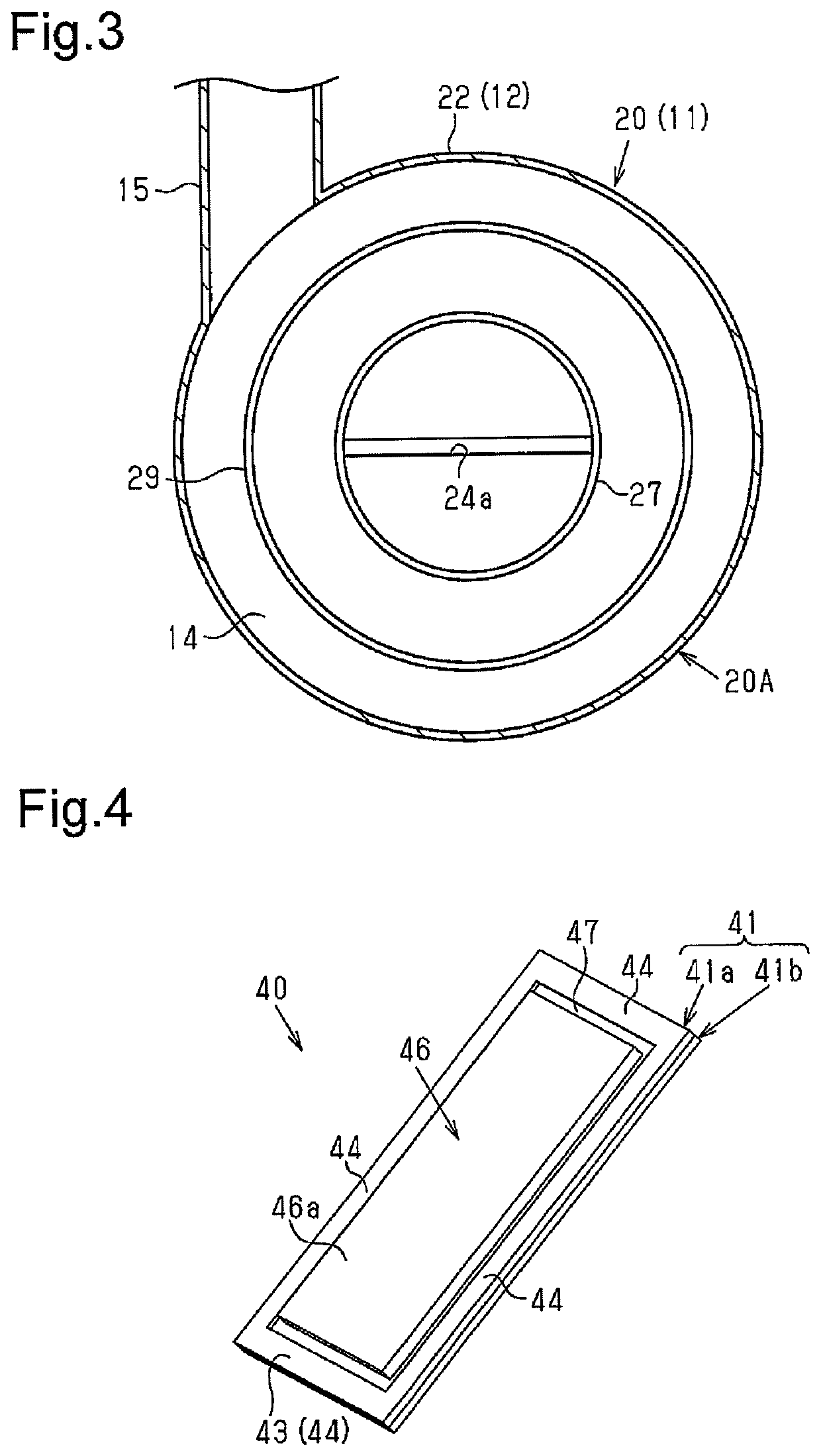
[0058]As shown in FIG. 6, the frame 44 includes two pillars 45 at portions that are not inserted into the insertion recess 24a. The two pillars 45 extend in the axial direction of the filter element 50. Each pillar 45 tapers in width as the pillar 45 extends distally from the fixing portion 43. A basal end of the pillar 45 is fixed to the inner surface of the case body 20A.

[0059]The second embodiment of the cylindrical air cleaner for an internal combustion engine has the advantages described below in addition to the advantages (1) through (5) of the first embodiment.

[0060](6) The adsorbent filter assembly 40 includes the frame 44, which is disposed about a periphery of the adsorbent filter 46. The frame 44 includes the two pillars 45 extending in the axial direction of the filter element 50. Each of the two pillars 45 tape...

modified examples

[0064]The above embodiments may be modified as follows.

[0065]The adsorbent filter 46 may be arranged so that the opposite planes 46a, 46b of the adsorbent filter 46 are at an angle with the projection direction of the airflow meter 60.

[0066]The layer structure of the adsorbent filter 46 may be changed, for example, by omitting the glass fiber nets. The material forming the adsorbent layer only needs to adsorb evaporated fuel. Thus, an adsorbent differing from activated carbon such as zeolite may be used.

[0067]The adsorbent filter 46 may be arranged so as not to extend through the axis of the filter element 50.

[0068]The adsorbent filter 46 may be inclined from the axial direction of the filter element 50.

[0069]The shape of the adsorbent filter 46 may be changed from the rectangular plate to, for example, a trapezoidal plate.

[0070]The process for fixing the fixing portion 43 of the adsorbent filter assembly 40 to the bottom wall 14 of the case body 20A is not limited to vibration weld...


PUM

PropertyMeasurementUnit
widthaaaaaaaaaa
air pressure lossaaaaaaaaaa
circumferenceaaaaaaaaaa

Abstract

A cylindrical air cleaner for an internal combustion engine includes a cylindrical housing including a circumferential wall having an inlet, a top wall having an outlet, and a bottom wall opposed to the top wall. There is a tubular filter element accommodated in the housing. A planar adsorbent filter to adsorb evaporated fuel of the internal combustion engine is located at an inner side of the filter element and extends in an axial direction of the filter element. The adsorbent filter includes a basal end portion fixed to an inner surface of the bottom wall. An inner surface of the filter element is spaced apart from each of opposite planes of the adsorbent filter by a gap that allows air to reach the outlet without passing through the adsorbent filter.

Description

BACKGROUND OF THE INVENTION[0001]The present invention relates to a cylindrical air cleaner arranged in an intake air passage of an internal combustion engine.[0002]A prior art cylindrical air cleaner for an internal combustion engine includes a cylindrical housing and a tubular filter element accommodated in the housing. The housing includes a circumferential wall having an inlet, a top wall having an outlet, and a bottom wall opposed to the top wall.[0003]The tubular filter element includes a pleated filter portion, which is formed by pleating a filter medium sheet, and two sealing portions, which are arranged on opposite ends of the filter portion in an axial direction to seal between the top wall and the bottom wall of the housing.[0004]Japanese Laid-Open Patent Publication No. 2001-123897 discloses a filter element that includes a filter portion and an inner tube, which is arranged at an inner side of the filter portion. The inner tube includes an adsorbent, which adsorbs evapo...

Claims


Application Information

Patent Timeline
Patent Type & Authority Patents(United States)
IPC IPC(8): B01D53/04F02M35/02F02M35/024B01D46/52B01D46/00B01D46/24
CPCB01D46/521F02M35/02425B01D46/0036F02M35/02483F02M35/021B01D53/0415B01D46/2411F02M35/0245B01D2253/102B01D2279/60B01D2259/4516B01D2257/702F02M35/0201F02M35/0202F02M35/024F02M35/02416F02M35/042
Inventor MORIKAWA, HIROAKI
Owner TOYOTA BOSHOKU KK
Why Eureka
Try Eureka