Tubular air cleaner for internal combustion engine

a technology of internal combustion engine and adsorbent filter, which is applied in the direction of machines/engines, combustion-air/fuel-air treatment, and separation processes, etc., can solve the problems of limited flow resistance and increase in airflow resistance caused by adsorbent filter, and achieve the effect of reducing air pressure loss and increasing airflow resistan

Active Publication Date: 2020-08-25
TOYOTA BOSHOKU KK
View PDF9 Cites 0 Cited by
  • Summary
  • Abstract
  • Description
  • Claims
  • Application Information

AI Technical Summary

Benefits of technology

[0005]The filter element described in Japanese Laid-Open Patent Publication No. 2001-123897 has the drawback of increasing the airflow resistance. The reason is that although the inner tube has a number of air holes, the inner tube blocks a passage through which the air flows. Therefore, there is room for improvement to reduce the air pressure loss.
[0006]It is an object of the present invention to provide a tubular air cleaner for an internal combustion engine that reduces air pressure loss.
[0008]With this structure, when air flows through the filter element into the inner side of the filter element, the air is allowed to reach the outlet without passing through the adsorbent filter. Thus, when air flows through the inner side of the filter element, an increase in the flow resistance caused by the adsorbent filter will be limited. Consequently, the air pressure loss is reduced.
[0009]Additionally, in the above structure, the adsorbent filter assembly includes the adsorbent filter and the fixing portion, and the cap body includes the outlet. Thus, when the air cleaner is destined for a location that requires the adsorbent filter, the cap body to which the adsorbent filter assembly is coupled is used as the cap. When the air cleaner is destined for a location that does not require the adsorbent filter, the adsorbent filter assembly is not coupled to the cap body. That is, only the cap body may be used as the cap. This simplifies the structure of the adsorbent filter assembly. Also, the same cap body may be used regardless of whether or not the adsorbent filter is coupled to.

Problems solved by technology

The filter element described in Japanese Laid-Open Patent Publication No. 2001-123897 has the drawback of increasing the airflow resistance.
Thus, when air flows through the inner side of the filter element, an increase in the flow resistance caused by the adsorbent filter will be limited.

Method used


Image

  • Tubular air cleaner for internal combustion engine
  • Tubular air cleaner for internal combustion engine
  • Tubular air cleaner for internal combustion engine

Examples


first embodiment

[0018]A first embodiment will now be described with reference to FIGS. 1 to 4.

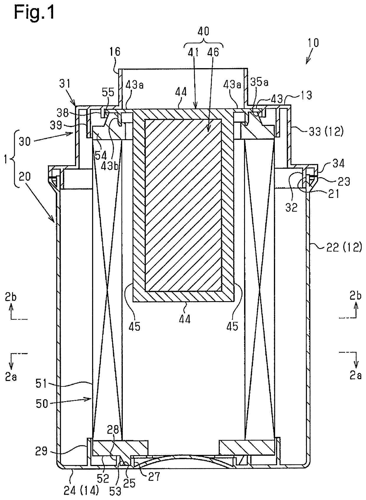
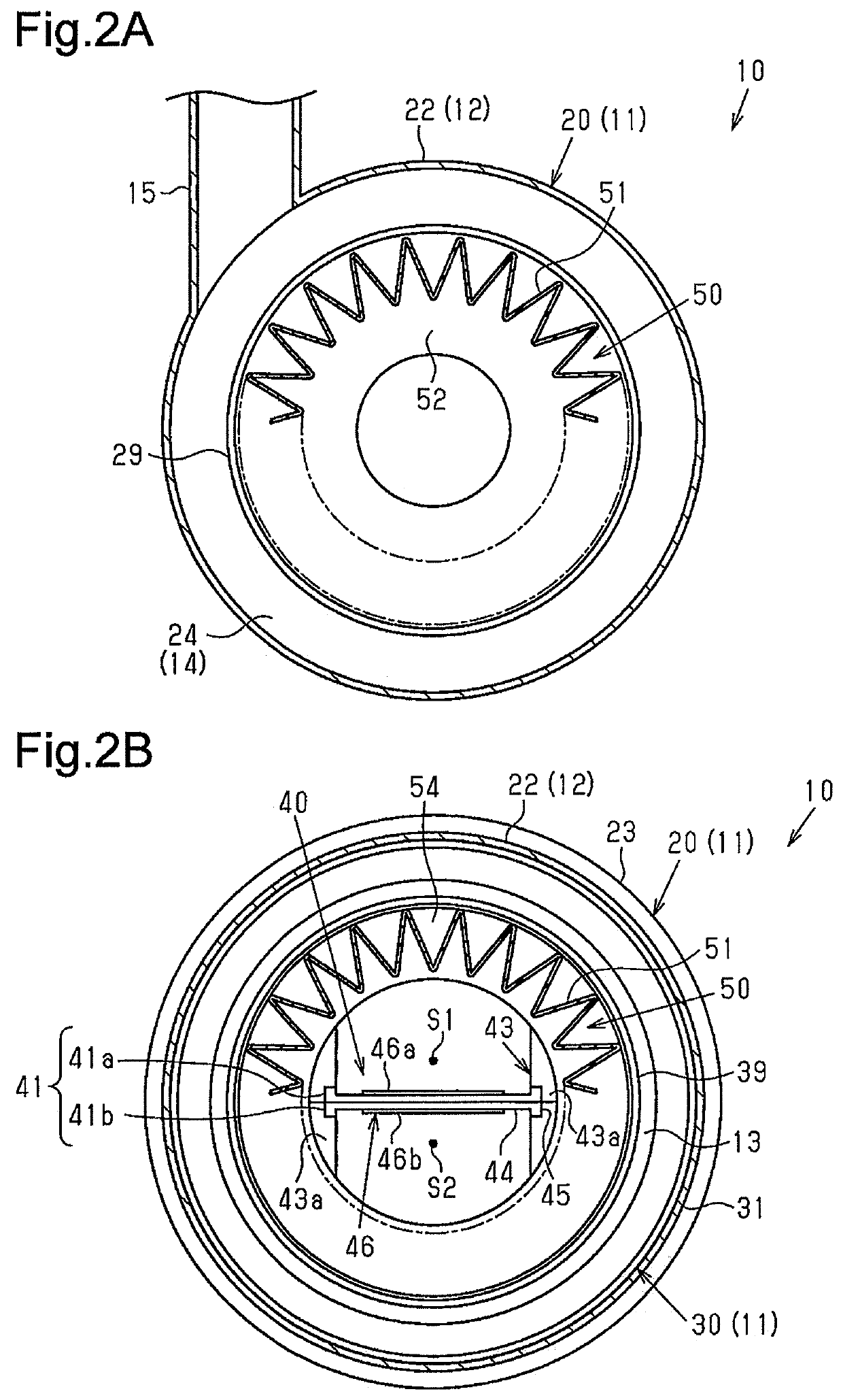
[0019]As shown in FIGS. 1, 2A, and 2B, a tubular air cleaner (hereafter, referred to as air cleaner 10) is arranged in an intake air passage of the internal combustion engine and includes a tubular housing 11. The tubular housing 11 includes a circumferential wall 12 including an inlet 15, a top wall 13 including an outlet 16, and a bottom wall 14 opposed to the top wall 13. A tubular filter element 50 is accommodated in the housing 11.

[0020]Filter Element 50

[0021]As shown in FIGS. 1, 2A, and 2B, the filter element 50 includes a pleated tubular filter portion 51, which is formed by pleating a filter medium sheet such as a non-woven cloth or filter paper, a first sealing portion 52, and a second sealing portion 54, each of which is discoid and has a center hole. The first sealing portion 52 and the second sealing portion 54 are located on one end and another end of the filter portion 51 in an axial directio...

second embodiment

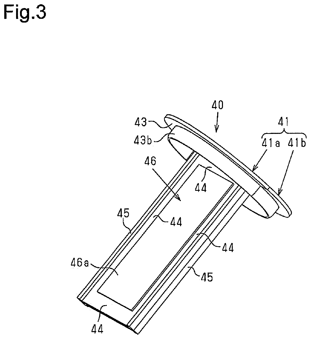
[0055]A second embodiment of an adsorbent filter assembly 40 will now be described focusing on the differences from the first embodiment with reference to FIG. 5.

[0056]As shown in FIG. 5, in the same manner as the first embodiment, the holding member 41 of the present embodiment includes the fixing portion 43, the frame 44, and the pillars 45. However, the holding member 41 of the present embodiment does not include the two half bodies 41a, 41b and is formed integrally. Additionally, each pillar 45 has a width tapered toward the distal side, which is distant from the fixing portion 43.

[0057]The peripheral edge portion 47 of the adsorbent filter 46 is bonded to an outer surface of the frame 44 to form the adsorbent filter assembly 40.

[0058]The second embodiment of the tubular air cleaner for an internal combustion engine has the advantages described below in addition to the advantages (1) through (3) of the first embodiment.

[0059](4) The adsorbent filter assembly 40 includes the fram...

third embodiment

[0063]A third embodiment of an air cleaner 10 will now be described focusing on the differences from the first embodiment with reference to FIG. 6.

[0064]As shown in FIG. 6, the outlet 16 includes an attachment slot 16a used for attachment of an airflow meter 60, which detects the intake air amount of the internal combustion engine.

[0065]In the present embodiment, the airflow meter 60 projects through the attachment slot 16a into the outlet 16. The adsorbent filter 46 is arranged parallel to the projection direction of the airflow meter 60.

[0066]The third embodiment of the tubular air cleaner for an internal combustion engine has the advantages described below in addition to the advantages (1) through (3) of the first embodiment.

[0067](5) The adsorbent filter 46 is arranged parallel to the projection direction of the airflow meter 60, which projects through the attachment slot 16a into the outlet 16.

[0068]With this structure, when air that has passed through the gaps S1, S2, which ar...


PUM

PropertyMeasurementUnit
circumferenceaaaaaaaaaa
widthaaaaaaaaaa
air pressure lossaaaaaaaaaa

Abstract

A tubular air cleaner for an internal combustion engine includes a housing and a filter element. The housing includes a case and a cap coupled to the case in a removable manner. The cap includes a cap body and an adsorbent filter assembly. The adsorbent filter assembly includes a planar adsorbent filter, which adsorbs evaporated fuel of the internal combustion engine, and a fixing portion. The adsorbent filter is located at an inner side of the filter element and extends in an axial direction of the filter element. The inner surface of the filter element is spaced apart from each of opposite planes of the adsorbent filter by a gap that allows air to reach an outlet without passing through the adsorbent filter.

Description

BACKGROUND ART[0001]The present invention relates to a tubular air cleaner arranged in an intake air passage of an internal combustion engine.[0002]A prior art tubular air cleaner for an internal combustion engine includes a tubular housing and a tubular filter element. The housing includes a circumferential wall including an inlet, a top wall including an outlet, and a bottom wall opposed to the top wall. The filter element is accommodated in the housing.[0003]The tubular filter element includes a pleated tubular filter portion, which is formed by pleating a filter medium sheet, and two sealing portions, which are arranged on opposite ends of the filter portion in an axial direction to seal the space between the top wall and the bottom wall of the housing.[0004]Japanese Laid-Open Patent Publication No. 2001-123897 discloses a filter element that includes a filter portion and an inner tube, which is arranged at an inner side of the filter portion. The inner tube includes an adsorben...

Claims


Application Information

Patent Timeline
Patent Type & Authority Patents(United States)
IPC IPC(8): F02M35/02F02M25/08B01D46/24B01D53/04B01D46/00B01D46/52F02M35/024
CPCF02M35/0201B01D53/0415F02M35/02483F02M25/089B01D46/0036B01D53/0407B01D46/2411B01D46/521F02M25/0854B01D2259/4566B01D2279/60B01D2253/102B01D2257/702F02M35/02416F02M35/02441F02M35/0245
Inventor MORIKAWA, HIROAKI
Owner TOYOTA BOSHOKU KK
Why Eureka
Try Eureka