Engineering tool coordination device, engineering tool coordination method, and non-transitory computer readable storage medium

Active Publication Date: 2018-05-03
HABCO IND INC +1
View PDF4 Cites 9 Cited by
  • Summary
  • Abstract
  • Description
  • Claims
  • Application Information

AI Technical Summary

Benefits of technology

[0006]An engineering tool coordination device may include a first tool interface configured to acquire first data having a first data format usable to an engineering tool, the engineering tool being configured to engineer a control program executed in a control device configured to control an operation of a plant, a data converter configured to convert the first data acquired by the first tool interface into second data usable to the control program, the second data having a second data format different from the first data format, a program provider configured to provide the second data converted by the data converter to the co

Problems solved by technology

However, since a method of defining a logic and a data format used in a control program is different depending on a type or the like of a control device, an engineering too

Method used


Image

  • Engineering tool coordination device, engineering tool coordination method, and non-transitory computer readable storage medium
  • Engineering tool coordination device, engineering tool coordination method, and non-transitory computer readable storage medium
  • Engineering tool coordination device, engineering tool coordination method, and non-transitory computer readable storage medium

Examples


first embodiment

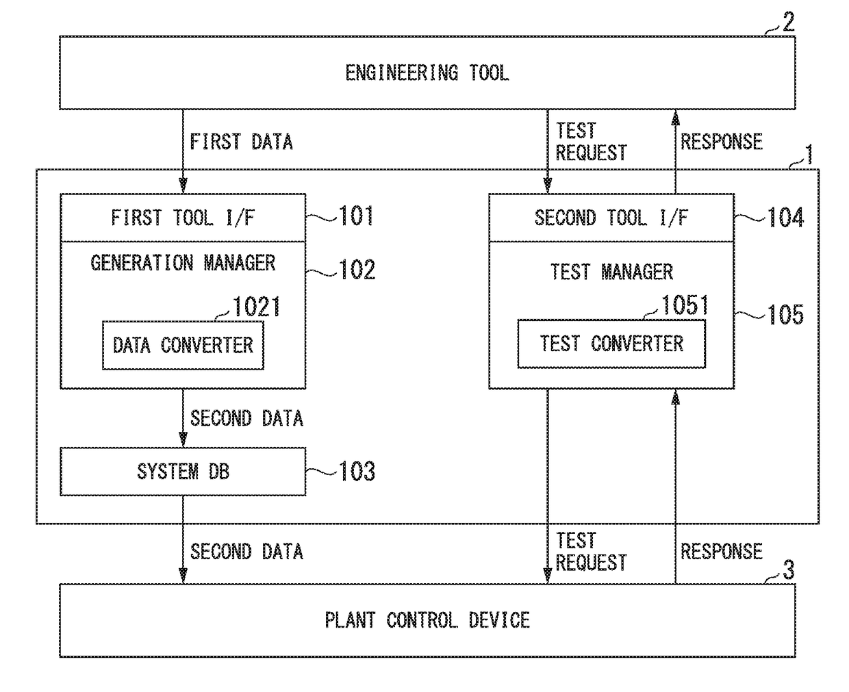
[0057]Next, a coordination function of an engineering tool coordination device 1 according to a first embodiment will be described using FIG. 4. FIG. 4 is a diagram illustrating an example of a coordination function of the engineering tool coordination device 1 according to the first embodiment. Functions illustrated in FIG. 4 are obtained by extracting the functions of the engineering tool coordination device 1 described with reference to FIG. 3.

[0058]In FIG. 4, the engineering tool coordination device 1 includes a first tool I / F 101, a generation manager 102, a data converter 1021, a system DB 103, a second tool I / F 104, and a test manager 105.

[0059]The first tool I / F 101 includes an I / F corresponding to an engineering tool 2 and acquires first data from the engineering tool 2. The data converter 1021 of the generation manager 102 converts the first data acquired in the first tool I / F 101 into second data and stores the converted second data in the system DB 103. The system DB 103...

second embodiment

[0070]Next, a coordination function of an engineering tool coordination device 1 according to a second embodiment will be described using FIG. 6. FIG. 6 is a diagram illustrating an example of the coordination function of the engineering tool coordination device 1 according to the second embodiment. Note that functions of constituent elements of FIG. 6 which are the same as those of FIG. 4 will be denoted with the same reference numerals and a description thereof will be omitted.

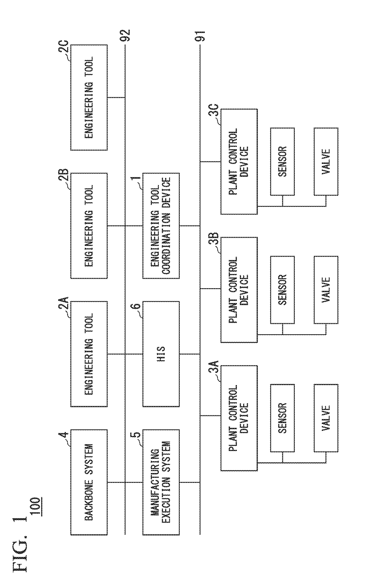
[0071]In FIG. 6, a plant 100A includes an engineering tool coordination device 1A, an engineering tool 2A, an engineering tool 2B, an engineering tool 2C, a plant control device 3A, and a plant control device 3B. Here, the engineering tool 2A, the engineering tool 2B, and the engineering tool 2C are set to be engineering tools of different types using different data formats.

[0072]The engineering tool coordination device 1A includes a first tool I / F 101A, a first tool I / F 101B, a first tool I / F 101C, a first ...


PUM


Abstract

An engineering tool coordination device includes a first tool interface configured to acquire first data having a first data format usable to an engineering tool, a data converter configured to convert the first data into second data usable to the control program, the second data having a second data format, a program provider configured to provide the second data to the control program, a second tool interface configured to acquire a first test request having a first test request format from the engineering tool, a test converter configured to convert the first test request into a second test request executable in the control program, the second test request having a second test request format, and a test manager configured to cause to execute an operation test program in the control program and to operate an operation test using the second data on a basis of the second test request.

Description

BACKGROUNDTechnical Fields[0001]The present invention relates to an engineering tool coordination device, an engineering tool coordination method, and a non-transitory computer readable storage medium.[0002]Priority is claimed on Japanese Patent Application No. 2016-210786, filed Oct. 27, 2016, the contents of which are incorporated herein by reference.Related Art[0003]In the related art, industrial plants such as chemical plants, plants which manage and control well sites such as gas wells and oil wells and the vicinity thereof, plants which manage and control hydraulic power generation, thermal power generation, nuclear power generation, and the like, plants which manage and control environmental power generation such as solar power generation and wind power generation, and plants which manage and control water supply and sewage, dams, and the like, and factories (hereinafter collectively referred to a “plant”) have been utilized, production control systems represented by a distri...

Claims


Application Information

Patent Timeline
IPC IPC(8): G05B23/02G05B19/042G05B19/048
CPCG05B23/02G05B19/0428G05B19/048G05B19/418G06F11/1608G06F11/3672G05B19/0426Y02P90/02G05B19/056G05B2219/36231
Inventor MURATA, HIDEKI
Owner HABCO IND INC
Why Eureka
Try Eureka