Division Synthesis

a division synthesis and logic technology, applied in the field ofbinary logic circuits, can solve the problem that logic units will rarely represent the most efficient logi

Active Publication Date: 2018-05-03
IMAGINATION TECH LTD
View PDF3 Cites 10 Cited by
  • Summary
  • Abstract
  • Description
  • Claims
  • Application Information

AI Technical Summary

Problems solved by technology

Such standard logic units will rarely represent the most efficient logic for calculating

Method used


Image

  • Division Synthesis
  • Division Synthesis
  • Division Synthesis

Examples


Embodiment Construction

[0090]The following description is presented by way of example to enable a person skilled in the art to make and use the invention. The present invention is not limited to the embodiments described herein and various modifications to the disclosed embodiments will be apparent to those skilled in the art.

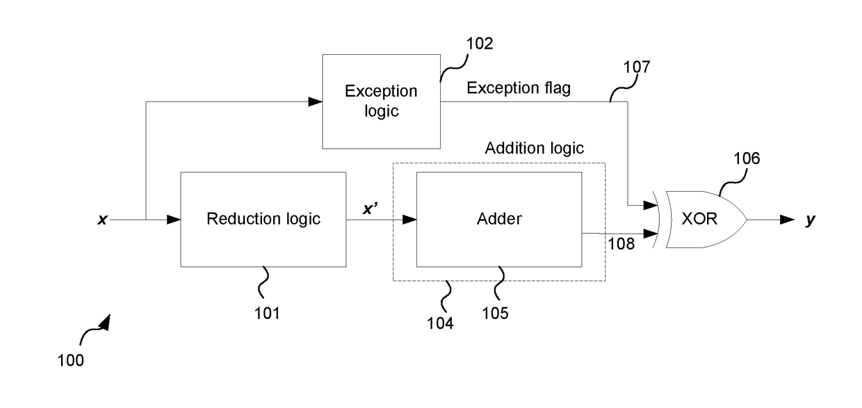
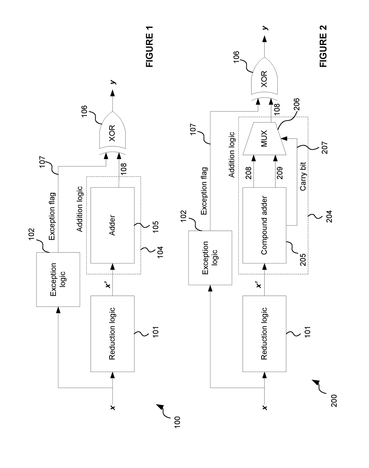
[0091]Examples described herein provide an improved binary logic circuit for calculating a ratio

div=xd

where x is a variable input and d is a fixed integer divisor. In the examples described herein, x is an unsigned variable integer input of known length w bits, d is a positive integer divisor of the form 2n±1, div is the output which has q bits. It will be appreciated that the principles disclosed herein are not limited to the particular examples described herein and can be extended using techniques known in the art of binary logic circuit design to, for example, signed inputs x, rounding schemes other than round to negative infinity, and divisors of related forms. For example, divis...


PUM


Abstract

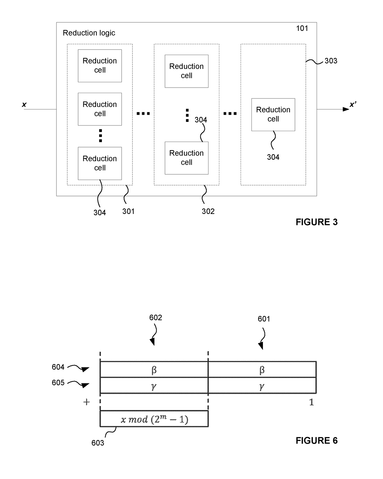
A binary logic circuit for determining the ratio x / d in accordance with a rounding scheme, where x is a variable integer input of bit length w and d is a fixed positive integer of the form 2n±1, the binary logic circuit being configured to form the ratio as a plurality of bit slices, the bit slices collectively representing the ratio, wherein the binary logic circuit is configured to generate each bit slice according to a first modulo operation for calculating mod(2n±1) of a respective bit selection of the input x and in dependence on a check for a carry bit, wherein the binary logic circuit is configured to, responsive to the check, selectively combine a carry bit with the result of the first modulo operation.

Description

BACKGROUND OF THE INVENTION[0001]This invention relates to a binary logic circuit for determining a ratiodiv=xd,particularly for the case in which x is an unsigned variable integer and d is a positive integer constant of the form 2n±1.[0002]It is a common requirement in digital circuits that hardware is provided for calculating a ratioxdfor some input x, where d is some constant known at design time. Such calculations are frequently performed and it is important to be able to perform them as quickly as possible in digital logic so as to not introduce delay into the critical path of the circuit.[0003]Binary logic circuits for calculating a ratioxdare well known. For example, circuit design is often performed using tools which generate circuit designs at the register-transfer level (RTL) from libraries of logic units which would typically include a logic unit for calculating a ratioxd.Such standard logic units will rarely represent the most efficient logic for calculatingxdin terms of...

Claims


Application Information

Patent Timeline
Patent Type & Authority Applications(United States)
IPC IPC(8): G06F7/535G06F7/499
CPCG06F7/535G06F7/49931G06F2207/5354G06F2207/5356G06F7/496G06F7/727G06F7/4873G06F7/4917
Inventor ROSE, THOMAS
Owner IMAGINATION TECH LTD
Why Eureka
Try Eureka