Rearview device with moveable head assembly

a head assembly and rearview device technology, applied in the field of head sections, can solve the problems of high manufacturing cost, poor wide angle view, and difficult to ensure achieve the effects of ensuring the maintenance of current end user functionality, enhancing packaging and performance, and reducing the size of the mirror

Inactive Publication Date: 2018-05-10
SMR PATENTS S A R L
View PDF0 Cites 19 Cited by
  • Summary
  • Abstract
  • Description
  • Claims
  • Application Information

AI Technical Summary

Benefits of technology

[0134]In an aspect, a head assembly of an external rear view device, in particular in the form of a mirror head of an external rear view mirror, can be articulated inboard / outboard and up / down using an articulation means. In particular, the articulation means may be a glass actuator, around a spherical joint, with spherical seats being provided between parts moving relative to each other such that they can rotate around two articulation axes perpendicular to each other having a common joint point. This ensures the maintenance of current end user functionality while offering significant smaller mirror size, with a reduction of size up to 30%. In addition, the unique layout of the internal mechanism with its spherical seats enhances packaging and performances.
[0135]The articulation assembly may also be supported and protected for impact using the spherical seats, in particular due to the arrangement of frame means between the articulation assembly and a casing of the head assembly. Because the casing is assembled from several casing elements, one of which is secured to the moveable part of the articulation assembly, this improves the weight distribution and reduces total housing frontal area on the vehicle which in turn improves aero performance and, thus, provides a higher fuel efficiency.
[0136]The pivot system used for the rear view device of an aspect of the invention with the single pivot point for two articulation axes permits a mirror adjustment while providing dynamic mirror performance and mirror impact support.

Problems solved by technology

Rear view means are typically made up of many components which require a number of different assembly parts and are complicated and expensive to manufacture.
In addition, when exposed to the outside environment, rear view means are subject to dirt or debris entering within the assembly.
In addition, while a rear view means may include improved protection from the outside environment such rear view means fail to provide a full and expansive field of view including a wide angle view as may be desired by a driver for viewing the driver's blind spot.

Method used


Image

  • Rearview device with moveable head assembly
  • Rearview device with moveable head assembly
  • Rearview device with moveable head assembly

Examples


Embodiment Construction

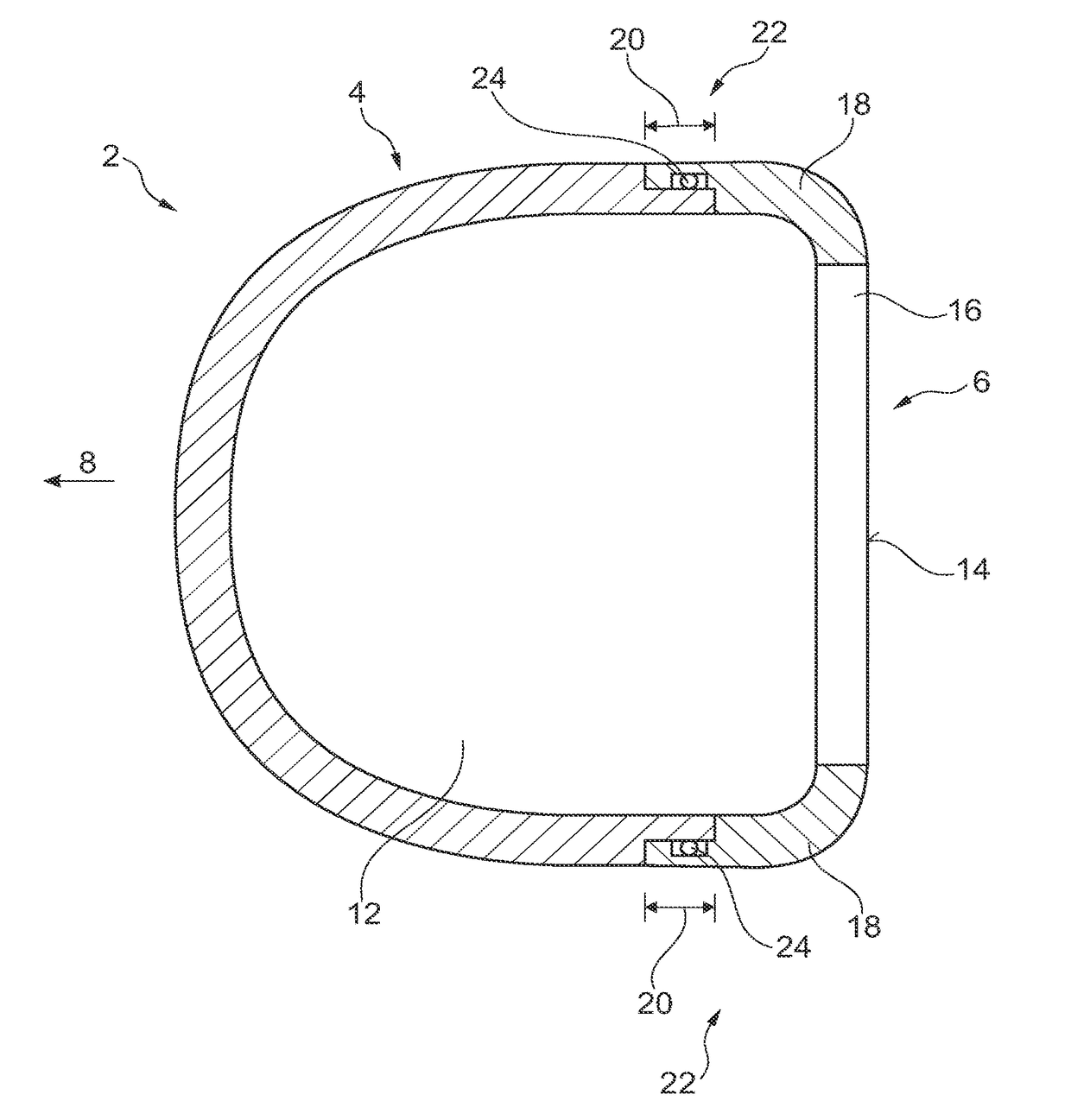
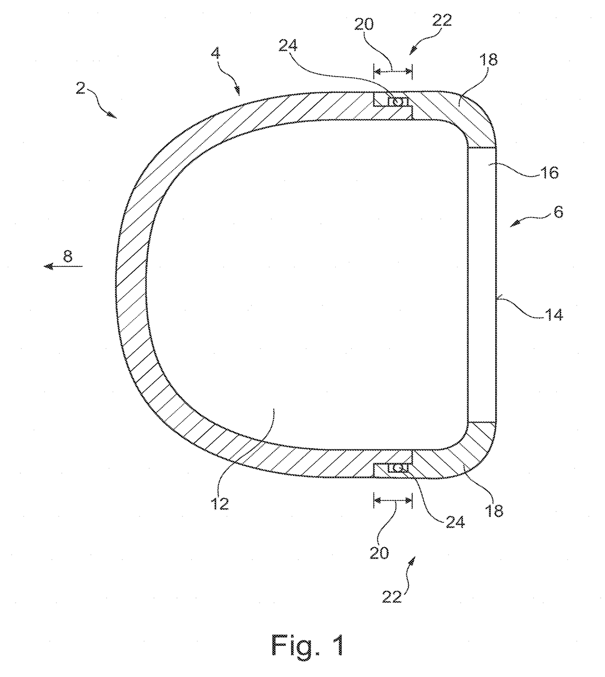
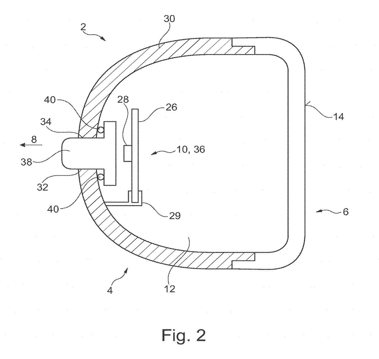
[0179]The following detailed description is provided to assist the reader in gaining a comprehensive understanding of the methods, apparatuses, and / or systems described herein. Accordingly, various changes, modifications, and equivalents of the systems, apparatuses and / or methods described herein will be suggested to those of ordinary skill in the art. Also, descriptions of well-known functions and constructions may be omitted for increased clarity and conciseness.

[0180]The term “rearview” is here defined as a view of the surrounding area, which is not in the field of view of the driver, i.e. the directions opposing, left, right, below and above of the viewing direction, but can also comprise the view in the direction of the viewing direction of the driver and / or any combinations of the directions.

[0181]The term “driver” and “driver of the vehicle” relates here to the person controlling the main parameters of the vehicle, such as for example direction, speed and / or altitude, e.g. no...


PUM


Abstract

A rear view device for a motor vehicle includes a base assembly for arrangement on the motor vehicle, a moveable head assembly attached to the base assembly, and an actuation mechanism, the actuation mechanism including a fixed part attached to the base assembly and a moveable part attached to the head assembly, where the actuation mechanism allows movement of the moveable part with respect to the fixed part in one or more axes.

Description

CROSS-REFERENCE TO RELATED APPLICATIONS[0001]This application is a continuation-in-part of U.S. patent application Ser. No. 15 / 603,751, filed May 24, 2017, which claims the benefit of foreign priority to European Patent Application No. 16198759.9, filed Nov. 14, 2016, each of which is hereby incorporated by reference in its entirety for all purposes; and this application is a continuation-in-part of U.S. patent application Ser. No. 15 / 607,894, filed May 30, 2017, which is a continuation-in-part of U.S. patent application Ser. No. 15 / 000,754, filed Jan. 19, 2016, which is a continuation-in-part of U.S. Patent Application No. 14 / 022,896, filed Sep. 10, 2013, which claims the benefit of foreign priority to German Patent Application No. 102012108480.7, filed Sep. 11, 2012, and is a continuation-in-part of U.S. patent application Ser. No. 15 / 439,188, filed Feb. 22, 2017, which is a continuation-in-part of U.S. patent application Ser. No. 14 / 936,024, filed Nov. 9, 2015, which is a continu...

Claims


Application Information

Patent Timeline
Patent Type & Authority Applications(United States)
IPC IPC(8): B60R1/08B60R1/12B60R1/07
CPCB60R1/081B60R1/1207B60R1/07B60R2001/1253B60R2300/8026B60R2001/1223B60R1/072B60R1/074
Inventor HERRMANN, ANDREASSCHMIERER, ARNEFIELD, SIMONLETTIS, ANDREWREHILL, GRAHAMSCOTT-COLLINS, CALLUMCHARLET, FRANCIS
Owner SMR PATENTS S A R L
Why Eureka
Try Eureka