
Automatic water-saving device for faucet

a technology of automatic water saving and faucet, which is applied in the direction of valve operating means/releasing devices, mechanical devices, multiple way valves, etc., can solve the problems of reducing the water discharge capacity of the faucet, unable to restore the water discharge capacity to a small amount, and unable to achieve the restoration of the small water discharge capacity. , to achieve the effect of increasing the water discharge capacity, small water discharge capacity and saving water

Inactive Publication Date: 2018-05-10
APLUS HARDWARE
View PDF0 Cites 0 Cited by
  • Summary
  • Abstract
  • Description
  • Claims
  • Application Information

AI Technical Summary

Benefits of technology

The invention is a faucet that saves water by only allowing water to flow through certain parts of the faucet when it is opened. When the faucet is closed, the positioning balls move back to their original position and close the mouths, allowing water to flow only through certain parts of the faucet again. This design ensures that water is only allowed to flow through certain parts of the faucet, which helps to save water and minimize waste.

Problems solved by technology

The water-saving device may decrease the water discharge capacity of the faucet.
However, the disadvantage of the water-saving device lies in that after the water discharge capacity is increased by the switch, the water discharge capacity can only be restored by pushing the switch again and the restoration to small water discharge capacity cannot be done by operating the water tap of the faucet.
Accordingly, the water-saving function of the water-saving device is lost.
That is, the water discharge capacity is small when the faucet is opened again.

Method used


Image

  • Automatic water-saving device for faucet
  • Automatic water-saving device for faucet
  • Automatic water-saving device for faucet

Examples


Embodiment Construction

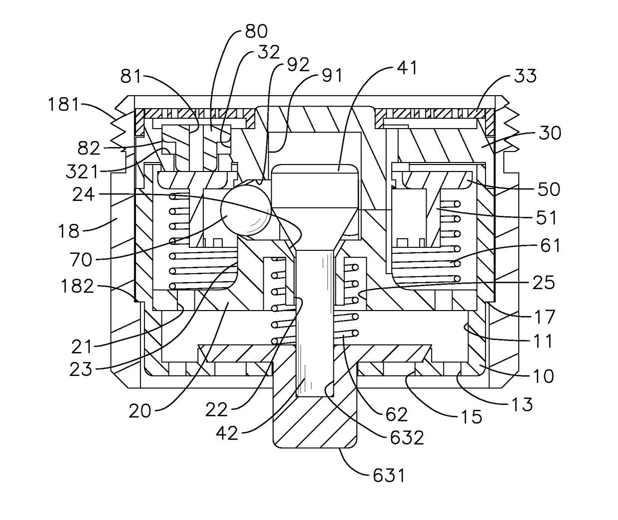
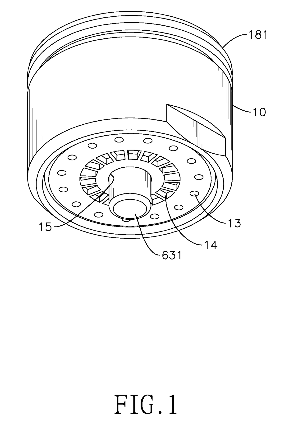
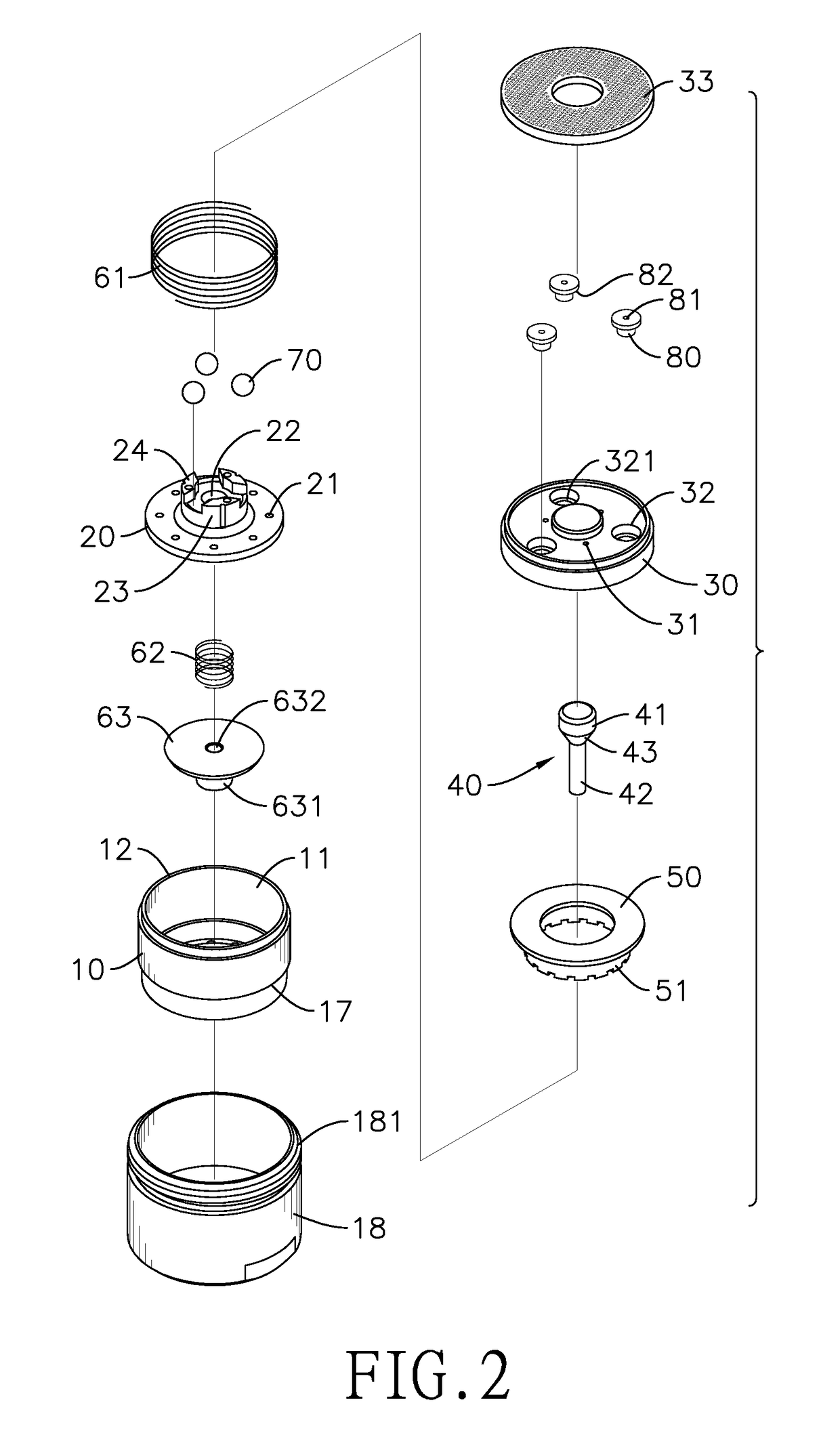
[0019]With reference to FIGS. 1 to 4, an automatic water-saving device of the present invention comprises a housing 10, a lower holder 20, an upper holder 30, an actuation space 91, multiple transverse tunnels 92, an actuation rod 40, a blocker 50, a first resilient member 61, and multiple positioning balls 70. In an embodiment, the automatic water-saving device further comprises a mounting shell 18, a baffle 63, a second resilient member 62, multiple plugs 80, and a filter 33.

[0020]With reference to FIGS. 1, 2, and 4, the housing 10 comprises a bottom wall, an inner space 11, a top opening 12, multiple first discharge holes 13, multiple second discharge holes 14, and a through hole 15. The first discharge holes 13, the second discharge holes 14, and the through hole 15 are formed through the bottom wall of the housing 10. In an embodiment, the through hole 15 is formed through a center of the bottom wall of the housing 10. The first discharge holes 13 are arranged at intervals and ...


PUM


Abstract

An automatic water-saving device has a housing, a lower holder, an upper holder, an actuation rod, a blocker, a first resilient member, and multiple positioning balls. The actuation rod, the blocker, the first resilient member, and the positioning balls are disposed between the lower and the upper holders. The lower and upper holders are disposed in the housing. Each of the lower and the upper holders has multiple holes for water flowing. The upper holder further has multiple mouths for water flowing. The automatic water-saving device has the advantage of automatically recovering the water discharge capacity back to small volume after manually adjusting the water discharge capacity to large volume. Hence, the water-saving function of the automatic water-saving device is enhanced and ensured, and the automatic water-saving device is convenient in use.

Description

CROSS-REFERENCE TO RELATED APPLICATION(S)[0001]This application is based upon and claims priority under 35 U.S.C. 119(a) from Taiwan Patent Application No. 105136412 filed on Nov. 9, 2016, which is hereby specifically incorporated herein by this reference thereto.BACKGROUND1. Technical Field[0002]The present invention relates to a water-saving device, and specifically to an automatic water-saving device for a faucet.2. Description of the Prior Art(s)[0003]With the rising environmental awareness, concepts of energy saving and conservation of resources have become dominant A variety of energy-saving or resource-economizing devices are manufactured and sold on the market.[0004]Among the issues in the environmental protection, economizing water resource is a significant one that deserves intensive attention. Hence, a water-saving device adapted for mounting on the outlet of a faucet is provided. The water-saving device may decrease the water discharge capacity of the faucet.[0005]Additi...

Claims


Application Information

Patent Timeline
Patent Type & Authority Applications(United States)
IPC IPC(8): F16K11/04F16K31/44E03C1/02
CPCF16K11/04E03C2001/026E03C1/02F16K31/44E03C1/08
Inventor CHUANG, YUNG-HUANG
Owner APLUS HARDWARE
Learn More