
Moisture removing apparatus for headlight

a technology of headlights and apparatuses, which is applied in the direction of lighting and heating apparatus, fixed installation, transportation and packaging, etc., can solve the problems of reducing the intensity of headlight illumination, corroding and damage of surrounding parts, and the use of fan installed inside the headlight requires additional energy for driving the fan, so as to prevent moisture from condensing and prevent performance degradation of the headlight

Active Publication Date: 2018-05-10
HYUNDAI MOTOR CO LTD
View PDF0 Cites 2 Cited by
  • Summary
  • Abstract
  • Description
  • Claims
  • Application Information

AI Technical Summary

Benefits of technology

The present invention is a moisture-removing apparatus for a headlight that can remove moisture from the headlight housing using electrolysis, thus solving the problem of moisture condensation and preventing degradation of the headlight performance. The apparatus can prevent moisture from condensing when high-humidity air is introduced during replacement or maintenance of the headlight. Additionally, by placing the apparatus where the headlight lens and housing are connected, and using a moisture-absorbing layer to collect moisture in the most-generated location, the apparatus can also decompose moisture.

Problems solved by technology

When condensation appears as droplets of water that flow down the inside of the headlight lens, the surrounding parts are corroded and damaged.
In addition, the droplets of water are repeatedly condensed and evaporated, thereby forming fog on the headlight lens while leaving a trail on the surface of the headlight lens and thus reducing intensity of illumination of the headlight.
However, use of fan installed inside the headlight requires additional energy for driving the fan.
When the inside of the headlight is vacuumized, the unit price of the headlight is increased, and the cost to repair the headlight also increases because the entire headlight must be replaced even when only the light source needs to be replaced.

Method used


Image

  • Moisture removing apparatus for headlight
  • Moisture removing apparatus for headlight
  • Moisture removing apparatus for headlight

Examples


Embodiment Construction

[0026]Hereinbelow, example embodiments of the present disclosure are described in detail with reference to the accompanying drawings. Throughout the drawings, the same reference numerals will refer to the same or like parts.

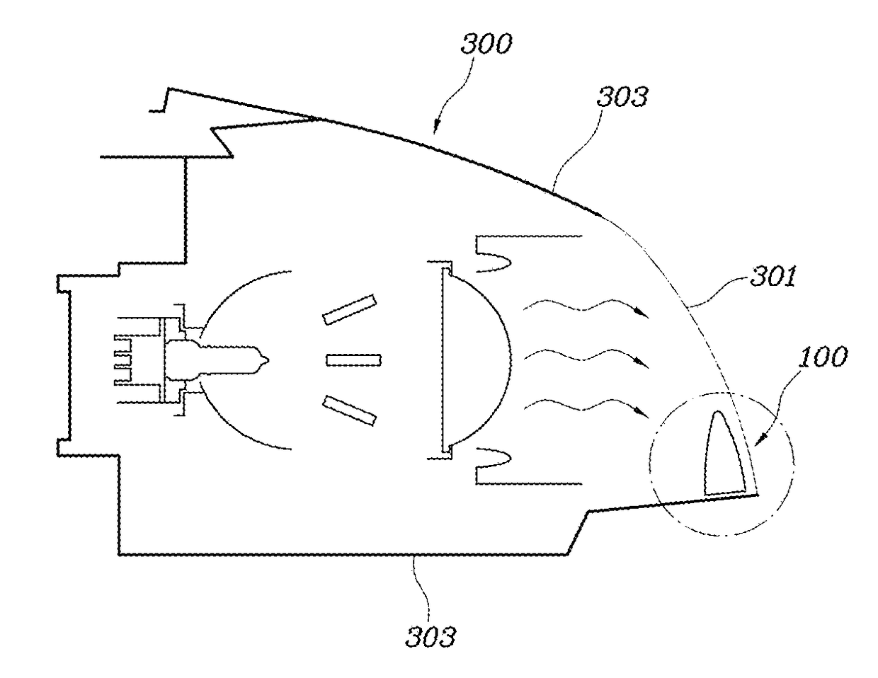
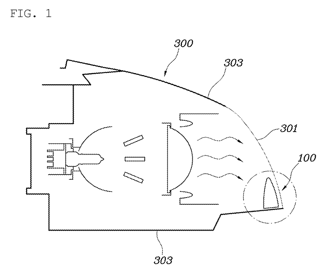
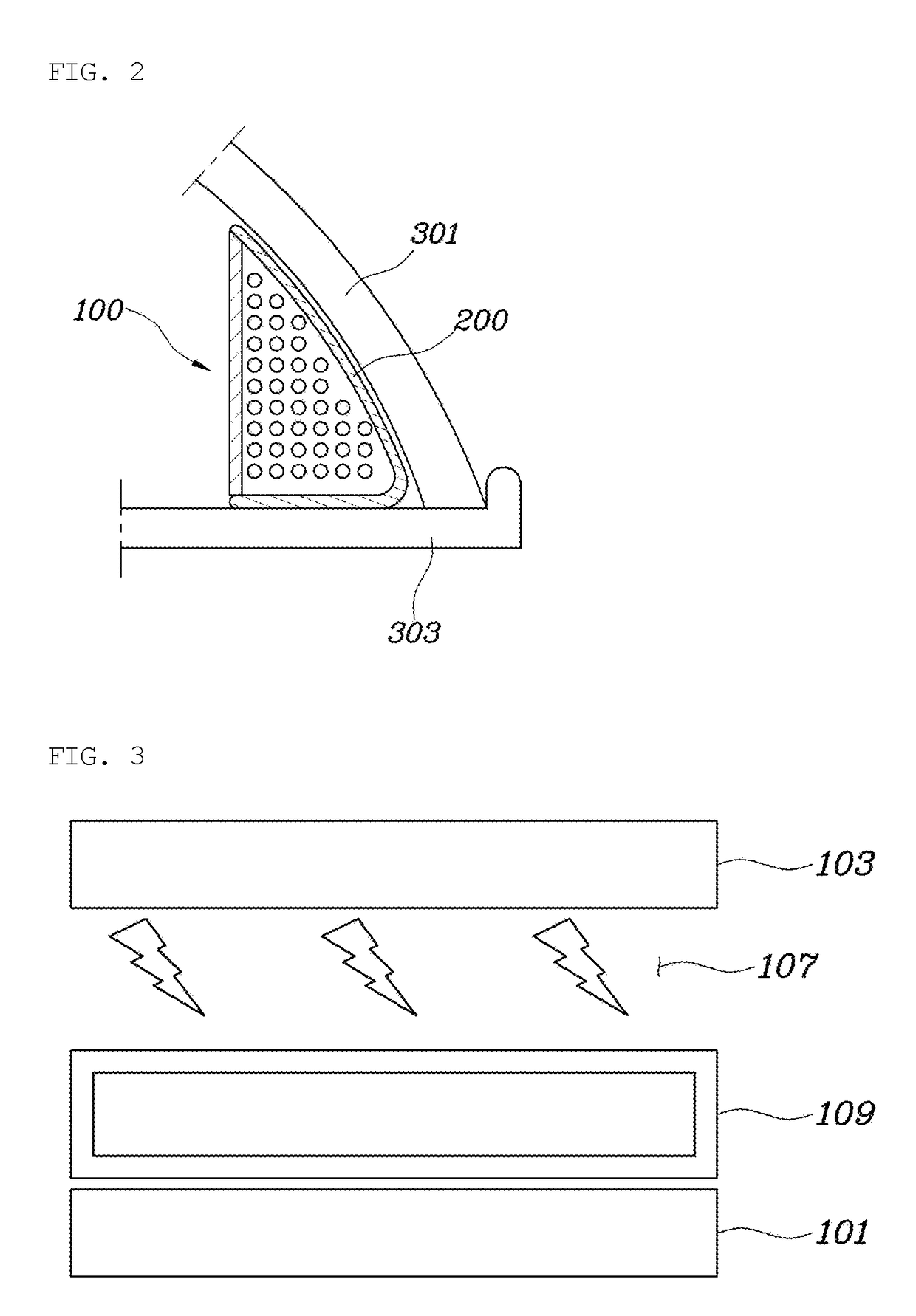
[0027]FIG. 1 is a view showing the configuration of a moisture-removing apparatus for a headlight according to an example embodiment. FIG. 2 is an enlarged view showing the moisture-removing apparatus for the headlight according to an example embodiment. FIG. 3 is a view showing a basic structure of the moisture-removing apparatus for the headlight according to an example embodiment. FIG. 4 is a cross-sectional view showing the moisture-removing apparatus for the headlight according to an example embodiment. FIG. 5 is an exploded perspective view showing the moisture-removing apparatus for the headlight according to an example embodiment.

[0028]The moisture-removing apparatus for the headlight according to the present an example embodiment of the present disclosur...


PUM

PropertyMeasurementUnit
distanceaaaaaaaaaa
temperatureaaaaaaaaaa
shapeaaaaaaaaaa

Abstract

Disclosed is a moisture-removing apparatus for a headlight, the apparatus comprising: a moisture decomposition module having a first electrode that is exposed inside a headlight housing and is connected to a first electrode of a power source; a second electrode that is connected to a second electrode of the power source; and an electric discharge air path in the space between the surface of the first electrode and the surface of the second electrode; and a moisture-absorbing layer; wherein the first electrode of the moisture decomposition module is coated with a dielectric material on a surface thereof; and wherein the moisture-absorbing layer is configured to correspond to a shape of one of the first and second electrodes of the moisture decomposition module, and to come into surface contact with one of the first and second electrodes of the moisture decomposition module.

Description

CROSS REFERENCE TO RELATED APPLICATION[0001]The present application claims benefit of and priority to Korean Patent Application No. 10-2016-0148689, filed Nov. 9, 2016, the entire contents of which is incorporated herein for all purposes by this reference.BACKGROUNDTechnical Field[0002]The present disclosure relates generally to a moisture-removing apparatus for a headlight. More particularly, the present disclosure relates to a moisture-removing apparatus for a headlight, the apparatus being capable of removing moisture condensed in a vehicle headlight by electrolysis.Description of the Related Art[0003]In general, light emitted from a light source inside a headlight of a vehicle can generate heat and thus heat up an interior of the headlight to a high temperature. Due to the difference in temperature between the headlight housing cooled by driving wind or a vehicle's surrounding environment and the heated interior of the headlight, moisture inside the headlight can easily reach a ...

Claims


Application Information

Patent Timeline
Patent Type & Authority Applications(United States)
IPC IPC(8): F21S8/10C25B9/17
CPCF21S48/33F21S45/50F21V31/00F21V31/04F21S45/10F21S45/33C08J5/22C08L27/18F21W2102/00F21S45/60
Inventor LEE, SANG SHINPARK, JAE WOOPARK, SO YOONOH, MAN JUKIM, JAE WOONGCHUNG, SO LA
Owner HYUNDAI MOTOR CO LTD
Learn More