
Acquisition and/or tracking of remote object

a remote object and acquisition technology, applied in the field of remote object acquisition and/or tracking, can solve the problems of null data, spurious data, and difficulty for operators to keep laser beams directed exactly at the target obj

Active Publication Date: 2018-05-10
OPENWORKS ENG LTD
View PDF1 Cites 1 Cited by
  • Summary
  • Abstract
  • Description
  • Claims
  • Application Information

AI Technical Summary

Benefits of technology

The present invention aims to solve or mitigate certain problems and disadvantages associated with related art. It provides at least one advantage over related art, and offers a method for achieving better performance and efficiency. The technical effects of the invention are described in detail in the following description and drawings.

Problems solved by technology

One problem with conventional laser rangefinders is that, due to movement of the operator and / or movement of the target object, it may be difficult for the operator to keep the laser beam directed exactly at the target object.
This may result in null data, for example if the beam is pointed at a location (e.g. the sky) where the beam is not reflected back to the rangefinder.
It may also result in spurious data, for example if the beam is pointed at an object (e.g. a foreground or background object) other than the target object.
Consequently, any measured distance may be unreliable.
This difficulty may be increased when the target object is a relatively large distance away and / or if the target object is moving relatively quickly.
Furthermore, it may be difficult for the operator to know whether the target object has been validly acquired, that is whether the beam is directed at the target object in a sufficiently accurate and stable manner so as to achieve a reliable distance measurement.
If the target object is moving, it may be difficult for the operator to know whether the target object is being validly tracked, that is whether the beam is moved so as to follow the target object in a sufficiently accurate and stable manner so as to achieve continuous distance measurements.

Method used

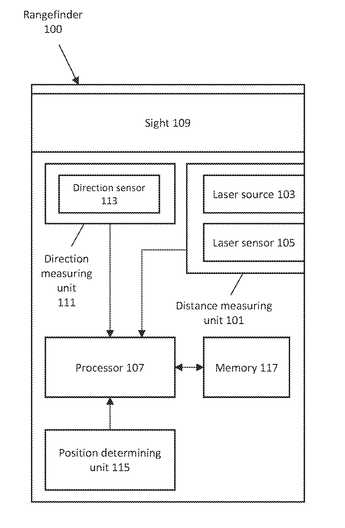
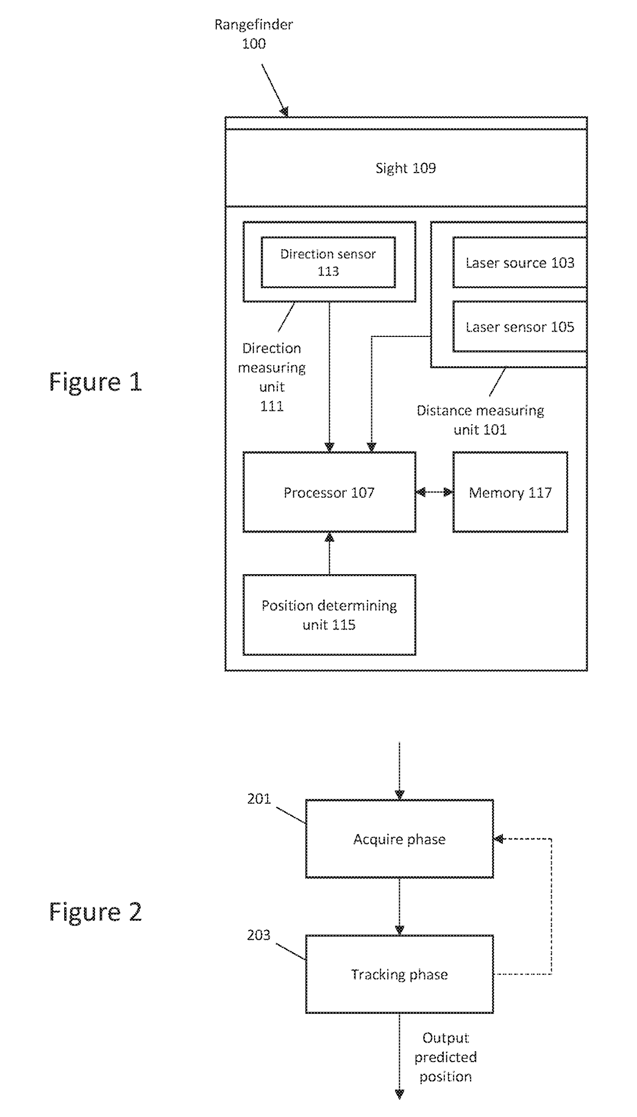
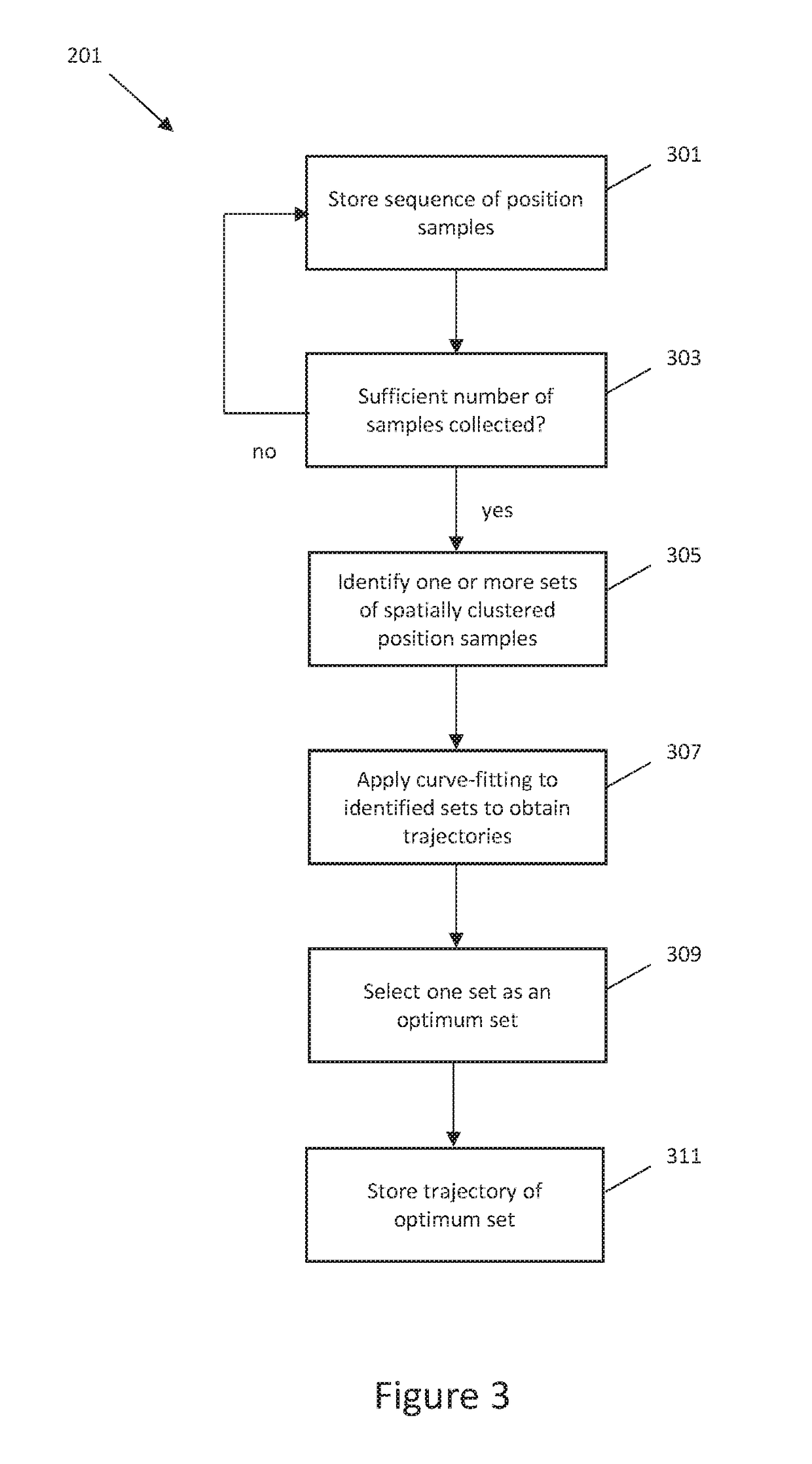

Image

  • Acquisition and/or tracking of remote object
  • Acquisition and/or tracking of remote object
  • Acquisition and/or tracking of remote object

Examples


Embodiment Construction

[0017]The following description of exemplary embodiments of the present invention, with reference to the accompanying drawings, is provided to assist in a comprehensive understanding of the present invention, as defined by the claims. The description includes various specific details to assist in that understanding but these are to be regarded as merely exemplary. Accordingly, those of ordinary skill in the art will recognize that various changes and modifications of the embodiments described herein can be made without departing from the scope of the present invention, as defined by the claims.

[0018]The terms and words used in this specification are not limited to the bibliographical meanings, but, are merely used to enable a clear and consistent understanding of the present invention.

[0019]The same or similar components may be designated by the same or similar reference numerals, although they may be illustrated in different drawings.

[0020]Detailed descriptions of elements, feature...


PUM


Abstract

A method for acquiring a remote object is provided. The method comprises obtaining a sequence of position samples of the remote object, identifying one or more sets of spatially clustered position samples from among the obtained position samples, and applying curve-fitting to at least one set of spatially clustered position samples to obtain a trajectory of the set of spatially clustered position samples. Also provided is a method for tracking a remote object. The method comprising obtaining an estimated trajectory of the object, obtaining one or more position samples of the object, comparing the obtained position samples with positions computed based on the estimated trajectory, and determining that the object is being tracked based on whether the obtained position samples are consistent with the computed positions.

Description

CROSS REFERENCE TO RELATED APPLICATIONS[0001]This application claims the benefit under 35 U.S.C. 119(a) to Great Britain Patent Application No. 1618045.7 filed Oct. 25, 2016, the entire disclosure of which is incorporated herein by reference in its entirety.FIELD OF THE INVENTION[0002]Certain exemplary embodiments provide a technique for acquisition of a remote object using a rangefinder. Certain exemplary embodiments provide a technique for tracking a remote object using a rangefinder.BACKGROUND OF THE INVENTION[0003]A rangefinder is a device capable of measuring the line-of-sight distance to a remote object. Rangefinders may employ various types of technology, for example based on laser, radar or sonar. In a typical laser rangefinder using a time-of-flight technique, the rangefinder transmits a laser pulse towards a target object, and the time taken for the pulse to be reflected off the object and travel back to a detector of the rangefinder is used to compute the distance to the ...

Claims


Application Information

Patent Timeline
Patent Type & Authority Applications(United States)
IPC IPC(8): G01C3/08G06F17/18G01C3/32H04B7/26G01S17/86
CPCG01C3/08H04B7/26G01C3/32G06F17/18G01S17/42G01S17/66G01S7/4808G01S17/86
Inventor DOWNARMSTRONG, NEIL ROCKCLIFFECROSSWILKINSON
Owner OPENWORKS ENG LTD
Learn More