Method and system for verifying panoramic images of implants

a panoramic image and imaging technology, applied in the field of methods and systems for verifying panoramic images of implants, can solve the problems of significant morbidity and/or mortality, large damage at the surgical site,

Active Publication Date: 2018-05-17
REMEX MEDICAL CORP
View PDF4 Cites 1 Cited by
  • Summary
  • Abstract
  • Description
  • Claims
  • Application Information

AI Technical Summary

Benefits of technology

[0005]According to one aspect of the present disclosure, a method for verifying panoramic images of implants and checking a relative position between an implant trajectory pattern and a surgical site pattern provides a pre-planning interface displaying step, an implant trajectory pattern adding step, an implant trajectory pattern adjusting step and a panoramic image verifying step. The pre-planning interface displaying step is for displaying at least one picture, a menu and a cursor on a screen, and the picture has the surgical site pattern. The implant trajectory pattern adding step is for moving the cursor to select an implant adding item of the menu by a user and then generating the implant trajectory pattern in the picture, and the implant trajectory pattern is located at a starting position. The implant trajectory pattern adjusting step is for controlling the cursor to adjust a position of the implant trajectory pattern and then move the implant trajectory pattern from the starting position to a target position in the picture. The panoramic image verifying step is for rotating the surgical site pattern around the implant trajectory pattern at a viewing angle according to the target position and the implant trajectory pattern as a central axis, and the viewing angle is greater than 0 degrees and smaller than or equal to 180 degrees.
[0006]According to another aspect of the present disclosure, a system for verifying panoramic images of implants and checking a relative posit

Problems solved by technology

If there is a slight error in the surgical operation, it may cause huge damage at a surgical site.
However, adjacent to the spine are numerous vital structures and organs, in par

Method used


Image

  • Method and system for verifying panoramic images of implants
  • Method and system for verifying panoramic images of implants
  • Method and system for verifying panoramic images of implants

Examples


Embodiment Construction

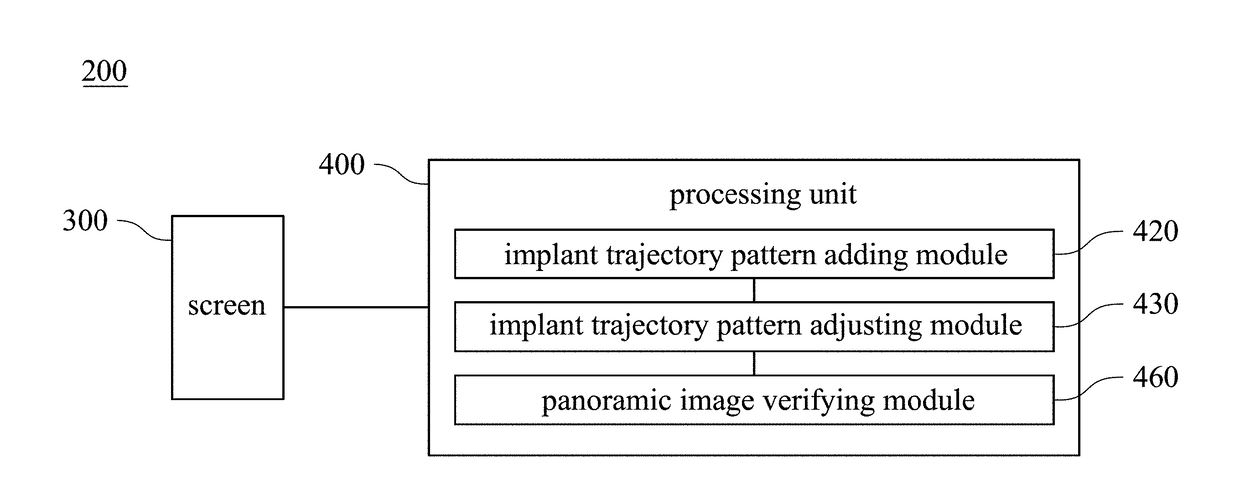
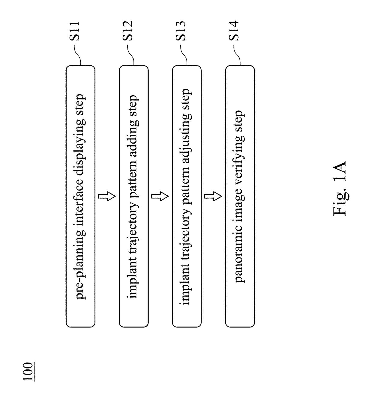
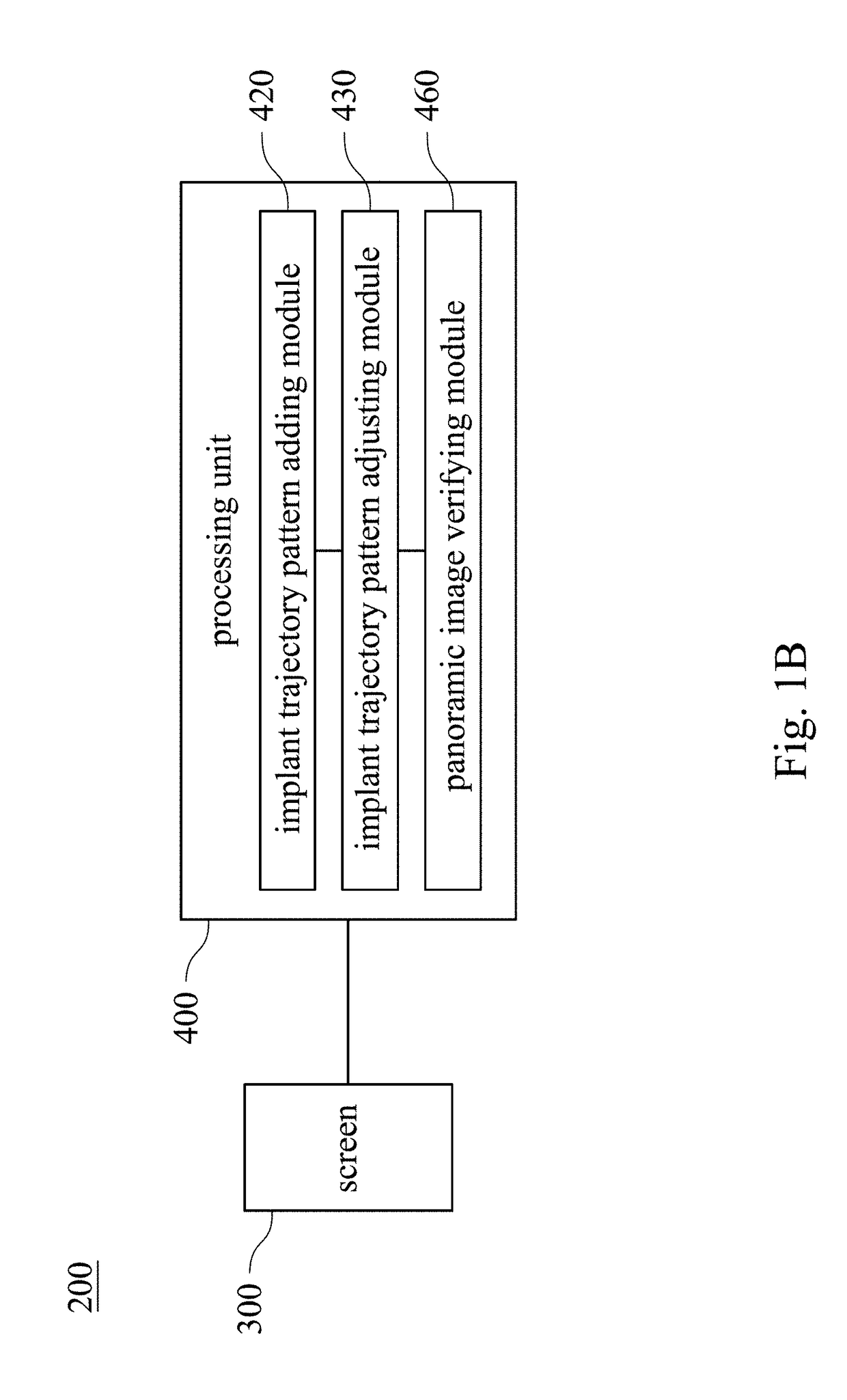
[0018]FIG. 1A shows a flow chart of a method 100 for verifying panoramic images of implants according to one embodiment of the present disclosure; FIG. 1B shows a block diagram of a system 200 for verifying panoramic images of implants according to one embodiment of the present disclosure; FIG. 3 shows a schematic view of an image of a screen 300 according to a first embodiment of the present disclosure; FIG. 4 shows a schematic view of an image of a screen according to a second embodiment of the present disclosure; FIG. 5 shows a schematic view of an image of a screen according to a third embodiment of the present disclosure; FIG. 6A shows a schematic view of an image of a screen according to a fourth embodiment of the present disclosure; FIG. 6B shows a schematic view of an image of a screen according to a fifth embodiment of the present disclosure; and FIG. 7 shows a schematic view of an image of a screen according to a sixth embodiment of the present disclosure. In addition, FIG...


PUM


Abstract

A pre-planning interface displaying step of a method for verifying panoramic images of implants is for displaying a picture, a menu and a cursor on a screen. An implant trajectory pattern adding step is for moving the cursor to select an implant adding item by a user and then generating the implant trajectory pattern in the picture. An implant trajectory pattern adjusting step is for controlling the cursor to adjust a position of the implant trajectory pattern and then move the implant trajectory pattern from a starting position to a target position in the picture. A panoramic image verifying step is for rotating the surgical site pattern around the implant trajectory pattern at a viewing angle according to the target position and the implant trajectory pattern as a central axis, and the viewing angle is greater than 0 degrees and smaller than or equal to 180 degrees.

Description

RELATED APPLICATIONS[0001]This application claims priority to U.S. Provisional Application Ser. No. 62 / 421,995 filed Nov. 14, 2016, and China application No. 201710281546.2 filed on Apr. 26, 2017, the disclosures of which are incorporated herein by reference in their entireties.BACKGROUNDTechnical Field[0002]The present disclosure relates to a method and a system for verifying images of implants. More particularly, the present disclosure relates to a method and a system for verifying panoramic images of implants.Description of Related Art[0003]In general medical institutions, a preoperative planning for surgery has already become a basic topic. Many surgical operations require high accuracy and rich experience. If there is a slight error in the surgical operation, it may cause huge damage at a surgical site.[0004]In a conventional surgical process, placement of bone screws into the human spine is a common surgical procedure to allow for a multitude of spinal surgeries to be performe...

Claims


Application Information

Patent Timeline
IPC IPC(8): A61B34/10A61B17/70A61B90/00G06F3/0482G06F3/0484G06T3/60G06T3/40
CPCA61B34/10A61B17/7001A61B90/37G06F3/0482G06F3/04845G06T2210/41G06T3/4038A61B2034/107A61B2090/364A61B2560/0487G06T2200/24G06T3/60G06F3/04815A61B2017/568A61B34/25
Inventor KAO, KUO-TUNGLIN, CHEN-TAICHENG, YING-YICHUANG, SHIH-CHANGCHIANG, CHIH-YEN
Owner REMEX MEDICAL CORP
Why Eureka
Try Eureka