Electric lock and clutch mechanism thereof

a technology of electric locks and clutch mechanisms, which is applied in the field of electric locks, can solve the problems of high production cost of electric locks of the prior art, difficult assembly, and complex structure of clutch mechanisms and gear transmission mechanisms, and achieve the effects of reducing production efficiency, reducing production cost, and improving production efficiency

Active Publication Date: 2018-05-17
TAIWAN FU HSING INDAL
View PDF1 Cites 4 Cited by
  • Summary
  • Abstract
  • Description
  • Claims
  • Application Information

AI Technical Summary

Benefits of technology

The present invention is about an electric lock that has a simple and easy to assemble clutch mechanism. The technical effect of this invention is that it provides a more efficient and reliable electric lock that is easy to assemble and use.

Problems solved by technology

However, the clutch mechanism and the gear transmission mechanism have complex structures and are not easy to assemble.
Therefore, the electric lock of the prior art has higher production cost and lower production efficiency.

Method used


Image

  • Electric lock and clutch mechanism thereof
  • Electric lock and clutch mechanism thereof
  • Electric lock and clutch mechanism thereof

Examples


Embodiment Construction

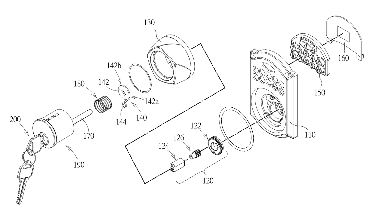
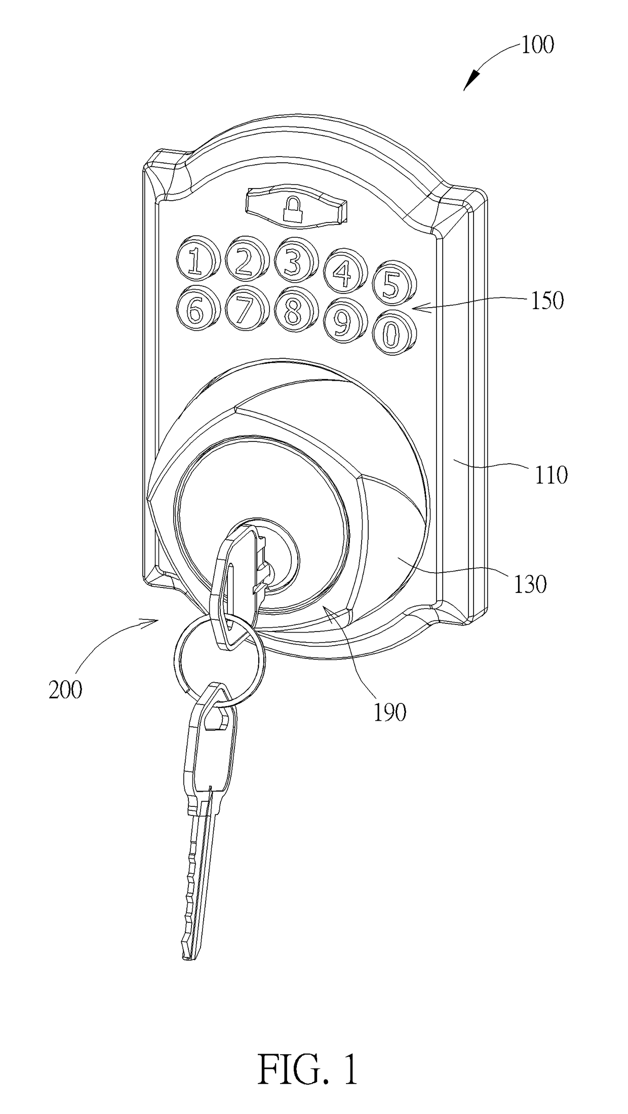
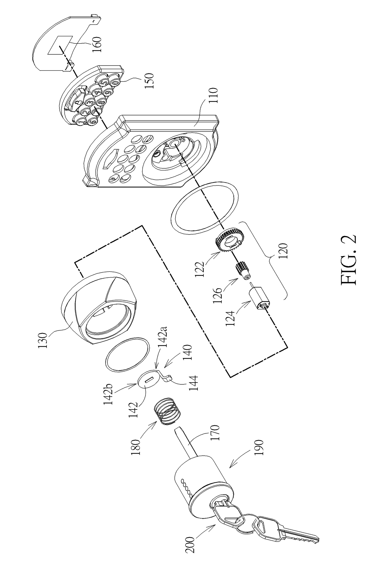
[0016]Please refer to FIG. 1 and FIG. 2 together. FIG. 1 is a diagram showing an electric lock of the present invention. FIG. 2 is an exploded view of the electric lock of the present invention. As shown in figures, the electric lock 100 of the present invention comprises a base 110, a driving module 120, a handle 130, a clutch member 140, an input interface 150 and a control unit 160. The electric lock 100 of the present invention can be fixed to a door for controlling movement of a latch on the door. The driving module 120 is arranged on the base 110. The driving module 120 comprises a driving member 122, a motor 124 and a transmission member 126. The driving member 122 is rotatable relative to the base 110. The transmission member 126 is connected between the motor 124 and the driving member 122 for transmitting power of the motor 124 to the driving member 122 in order to drive the driving member 122 to rotate. The handle 130 is installed on the base 110 in a rotatable manner. Th...


PUM


Abstract

An electric lock includes a base, a driving module, a handle and a clutch member. The driving module is arranged on the base. The driving module includes a driving member rotatable relative to the base, and a motor configured to drive the driving member to rotate. The handle is rotatably mounted to the base, and has a plurality of pushing structures. The clutch member includes a main body having a first end and a second end opposite to the first end, and a pushed structure formed on the first end of the main body. Wherein, when the motor drives the driving member to rotate in order to abut against the main body at a first position, the first end of the main body is tilted toward the handle, such that the pushing structure abuts against the pushed structure for pushing the clutch member to rotate when the handle is rotated.

Description

BACKGROUND OF THE INVENTION1. Field of the Invention[0001]The present invention relates to an electric lock, and more particularly, to an electric lock having a clutch mechanism which is simple and easy to assemble.2. Description of the Prior Art[0002]Generally, an electric lock utilizes a gear transmission mechanism to transmit a torsion torque outputted by a motor, so as to drive a clutch mechanism of the electric lock to engage with or disengage from a latch assembly. When the gear transmission mechanism is forwardly driven by the motor, a pushed structure on the gear transmission mechanism can drive the clutch mechanism to engage with the latch assembly of the electric lock. Accordingly, a torsion torque exerted by a handle can be transmitted to the latch assembly, so that a user can open the door by rotating the handle. When the gear transmission mechanism is reversely driven by the motor, a spring can drive the clutch mechanism to disengage from the latch assembly of the elect...

Claims


Application Information

Patent Timeline
IPC IPC(8): E05B47/00E05B1/00E05B49/00
CPCE05B47/0012E05B1/003E05B2047/0086E05B2047/002E05B49/00E05B3/00E05B15/00E05B2047/0026E05B47/0676E05B17/045E05B13/005E05B13/101E05B2047/0028
Inventor HUANG, LIEN-HSILEE, WEN-CHIEH
Owner TAIWAN FU HSING INDAL
Why Eureka
Try Eureka