Head-operated digital eyeglasses
Inactive Publication Date: 2018-05-24
XIE PEISHU
5 Cites 1 Cited by
AI-Extracted Technical Summary
Problems solved by technology
Additionally, a mobile phone and tablet PC can only display two-dimensional images, requiring the user to change his/her head gestures, thus limiting their respective ranges of application.
But the current digital eyeglasses are difficult to input the characters.
The speech recognition input method has the recognition error and poor interference immunity.
When both hands of the user are in...
Method used
[0079]Thus, infrared receiver (6A), infrared receiver (6B) and processor (2) can identify the user squint-blink instruction and single blink instruction. For squint-blink and a single blink, it is possible to eliminate the unconscious double blink of the human eyes and thereby reduce the risk of incorrect operation. Squint-blink is more relaxing and quicker than a blink. Squint-blink will not reduce the user's field of vision.
[0103]The display device may be transparent display device. Transparent display device can display the operation interface ...
Benefits of technology
[0061]In summary, the head-operated digital eyeglasses can fully free both hands and both feet of the user. Such eyeglasses allow the u...
Abstract
A pair of digital eyeglasses, including the following components: a left temple, a right temple, a left display device, a right display device, a left infrared transmitter, a right infrared transmitter, a left infrared receiver, a right infrared receiver, a head angular velocity detector, a torso angular velocity receiving interface, a processor, a memory, and a power supply. It allows the user to rapidly and accurately operate the pointer with the head and to output the image information into broad, three-dimensional space.
Application Domain
Input/output for user-computer interactionDetails for portable computers +3
Technology Topic
Infrared emitterAngular velocity +5
Image
Examples
- Experimental program(1)
Example
METHOD OF CARRYING OUT THE INVENTION
[0064]One preferred embodiment for the present invention is provided below, in combination with the attached figures for the description of the present invention.
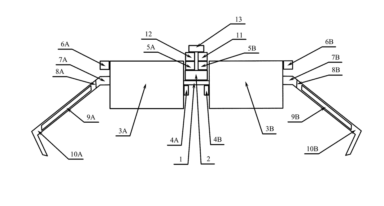
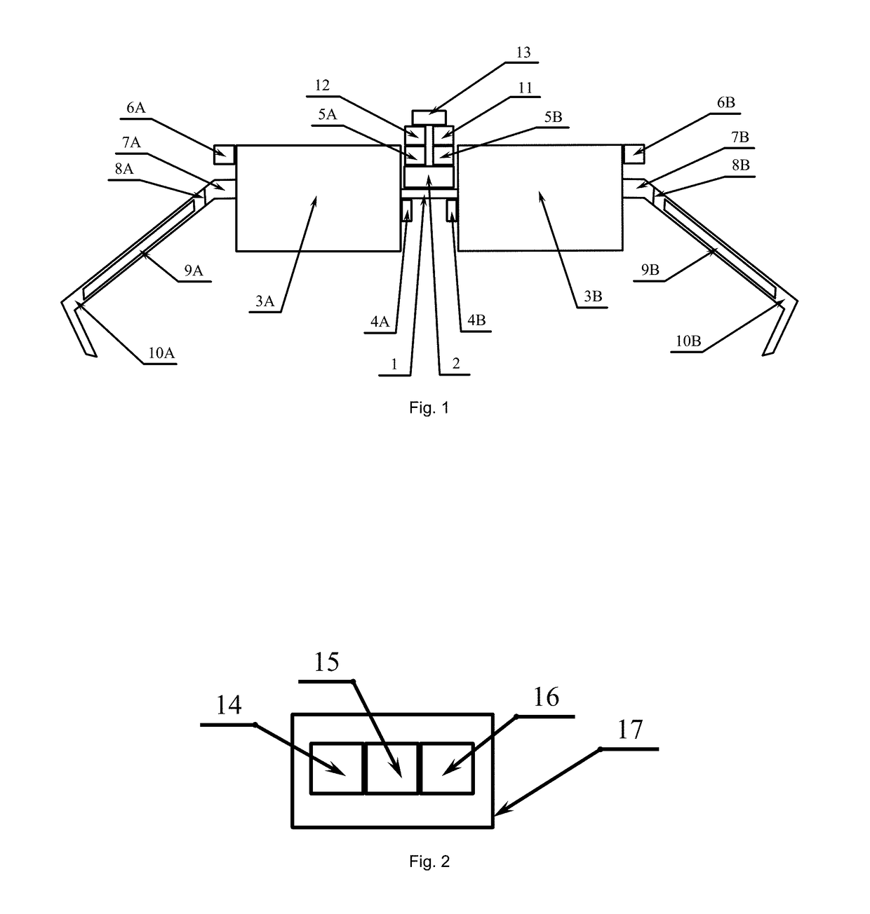
[0065]Digital eyeglasses embodiment includes two modules: display module and gyro tape. As shown in FIG. 1, the display module includes the following components: nose bridge (1), processor (2), display device (3A), display device (3B), nose pad (4A), nose pad (4B), infrared transmitter (5A), infrared transmitter (5B), infrared receiver (6A), infrared receiver (6B), pile tip (7A), pile tip (7B), hinge (8A), hinge (8B), power supply (9A), power supply (9B), temple (10A), temple (10B), head angular velocity gyroscope (11), torso angular velocity receiver (12), memory (13). As shown in FIG. 2, the gyro tape includes the following components: torso angular velocity gyroscope (14), torso angular velocity transmitter (15), power supply (16), and perspiration-resistant breathable tape (17).
[0066]In this paragraph, it is supposed that the user always wears the digital eyeglasses. The display device (3A) is situated in front of the user's left eye, and the display device (3B) is situated in front of the user's right eye.
[0067]Infrared transmitter can continuously emit the infrared, and can also emit the infrared in the fixed time interval. When the user opens the eyes, the infrared emitted by the infrared transmitter irradiates the eyes to reflect strong infrared light. When the user closes the eyes, the light ray emitted by the display device irradiates the eyes to reflect weak infrared light. Infrared receiver can convert the reflected infrared light into digital signal. The infrared transmitter (5A) emits infrared light onto the user's left eye, and the infrared receiver (6A) receives the infrared light reflected by the user's left eye. The infrared transmitter (5B) emits the infrared light onto the user's right eye, and the infrared receiver (6B) receives the infrared light reflected by the user's right eye. The infrared receiver (6A) and infrared receiver (6B) convert the received infrared intensity into one digital signal, and send it to the processor (2). Within the range of response, with the increase of the inputted infrared intensity, the digital signals outputted by the infrared receiver increase; otherwise, the digital signals outputted by the infrared receiver decrease.
[0068]Assume that 0 11 and 0 22. Assume that the sum of output signals of the infrared receiver (6A) is l and the sum of the output signal of the infrared receiver (6B) is r. If lϵ[q1,+∞), the processor (2) judges that the user's left eye is open; if lϵ[p1,q1), the processor (2) judges that the user's left eye squints; if lϵ[0,p1), the processor (2) judges that the user's left eye is closed. If rϵ[q2,+∞), the processor (2) judges that the user's right eye is open; if rϵ[p2,q2), the processor (2) judges that the user's right eye squints; if rϵ[0,p2), the processor (2) judges that the user's right eye is closed.
[0069]Assume that sϵ(0,3000). Some proper names are defined below.
[0070]Single squint-blink of the left eye: the user's right eye is open all the time, and the user's left eye cannot be closed. At the same time, the user's left eye is first open and then squints for s milliseconds and finally opens.
[0071]Single squint-blink of the right eye: the user's left eye is open all the time, and the user's right eye cannot be closed. At the same time, the user's right eye is first open and then squints for s milliseconds, and finally opens.
[0072]Single squint-blink: single squint-blink of the left eye or single squint-blink of the right eye.
[0073]Double squint-blink: the user's eyes cannot be closed. Moreover, the user's eyes open at the same time, then squint for s milliseconds at the same time, and finally open at the same time.
[0074]Squint-blink: single squint-blink or double squint-blink.
[0075]Single blink of the left eye: the user's right eye is open all the time. Moreover, the user's left eye is first open, then is closed for s milliseconds, and finally opens.
[0076]Single blink of the right eye: the user's left eye is open all the time. Moreover, the user's right eye is first open, then is closed for s milliseconds, and finally opens.
[0077]Single blink: single blink of the left eye or single blink of the right eye.
[0078]Double blink: the user's eyes open at the same time, then are closed for s milliseconds at the same time, and finally open at the same time.
[0079]Thus, infrared receiver (6A), infrared receiver (6B) and processor (2) can identify the user squint-blink instruction and single blink instruction. For squint-blink and a single blink, it is possible to eliminate the unconscious double blink of the human eyes and thereby reduce the risk of incorrect operation. Squint-blink is more relaxing and quicker than a blink. Squint-blink will not reduce the user's field of vision.
[0080]The head angular velocity gyroscope (11) and torso angular velocity gyroscope (14) are angular velocity detectors. The coordinate axis direction of the head angular velocity gyroscope (11) is consistent with that of the torso angular velocity gyroscope (14). The head angular velocity gyroscope (11) is a triaxial angular velocity gyroscope. Its support center serves as the origin of gyroscope coordinate system, and its main axis, horizontal axis and vertical axis constitute the coordinate axes of the gyroscope coordinate system. So, the head angular velocity gyroscope (11) can detect three-dimensional angular velocity vector. It is fixed on the digital eyeglasses in order to detect the three-dimensional angular velocity vector [a1,a2,a3] of the head. The torso angular velocity receiver (12) can receive the torso angular velocity coordinate axis direction and torso angular velocity vector by means of wired or wireless communication.
[0081]The torso angular velocity gyroscope (14) can be fixed on the perspiration-resistant breathable tape (17). Perspiration-resistant breathable tape (17) has the functions of perspiration-resistance and breathability. Perspiration-resistant breathable tape (17) can be attached to the epidermis of the torso, to fix the torso angular velocity gyroscope (14). Gyro tape allows the user to operate the digital eyeglasses in situations that are prone to bumping. The torso angular velocity gyroscope (14) can detect the three-dimensional angular velocity vector [b1,b2,b3] of the torso. The torso angular velocity gyroscope (14) can output the coordinate axis direction of the torso angular velocity and torso angular velocity vector to the torso angular velocity transmitter (15), and the torso angular velocity transmitter (15) can transmit the coordinate axis direction of the torso angular velocity and torso angular velocity vector by means of wired communication or wireless communication.
[0082]The processor (2) can detect the status of the torso angular velocity gyroscope (14), and send it to the user through the audio signal or video signal. The torso angular velocity gyroscope (14) has four statuses: angular velocity detector successfully connected, angular velocity detector connection failure, angular velocity detector successfully matched, and angular velocity detector matching failure.
[0083]If the torso angular velocity receiver (12) receives the torso angular velocity vector, then the processor (2) will notify the user: angular velocity detector is successfully connected; otherwise, the processor (2) will notify the user: angular velocity detector connection fails.
[0084]The head angular velocity gyroscope (11) can output the direction of the head angular velocity coordinate axis to the processor. The torso angular velocity gyroscope (14) can output the direction of the torso angular velocity coordinate axis to the processor (2). The processor (2) can calculate coordinate axis direction difference X of the head angular velocity gyroscope (11) and torso angular velocity gyroscope (14), and judge whether the angular velocity detector matching is successful. If X=0, then the coordinate axis direction of the head angular velocity gyroscope (11) is consistent with that of the torso angular velocity gyroscope (14), and the processor (2) will notify the user: angular velocity detector matching succeeds; if X≠0, then the coordinate axis direction of the head angular velocity gyroscope (11) is inconsistent with that of the torso angular velocity gyroscope (14), and the processor (2) will notify the user: angular velocity detector matching fails.
[0085]Assuming c1=a1−b1, c1=a1−b1, c1=a1−b1, the head relative angular velocity vector is [c1,c2,c3].
[0086]If the connection or matching of the angular velocity detector fails, the processor (2) sets torso angular velocity vector [b1,b2,b3] as zero vector [0,0,0]. At this moment, head relative angular velocity vector is [a1,a2,a3].
[0087]The processor (2) translates the origin of the coordinate system of the head angular velocity gyroscope (11) to the cervical apex of the user, by using the coordinate axis direction of the head angular velocity gyroscope (11) as that of the head coordinate system. Then, the processor (2) will build a three-dimensional head coordinate system for the head of the user. In whatever movement status for the user's head, the origin of the head coordinate system is always in the cervical apex of the user, and the coordinate axis direction of the head coordinate system is always consistent with the coordinate axis direction of the head angular velocity gyroscope (11).
[0088]The dead-ahead direction of the digital eyeglasses is consistent with the dead-ahead direction of the user's eyes. Assume that the head status is the initial status when the user stands up, the angle of rotation up and down for the user's head α meets
α ∈ [ - 4 π 5 , 4 π 5 ] ,
and the angle of left and right rotation of the user head β meets
β ∈ [ - 4 π 5 , 4 π 5 ] .
[0089]The operation interface is a virtual plane object in the three-dimensional space, it is stored in the form of electronic data in the memory. It is situated in front of the user's glasses. The front here includes dead-ahead front, upper front, lower front, left front and right front. The operation interface is always stable in relation to the head.
[0090]The pointer is situated on the two-dimensional operation interface, and its tip coordinate can be expressed with two-dimensional vector. The pointer may have two statuses for switching: “pointer disabled” and “pointer enabled.” When the pointer is in “pointer disabled” status, the pointer can neither move nor click; when the pointer is in “pointer enabled” status, the pointer can move and click.
[0091]The user may switch the pointer status by using the head. The method for the head to switch pointer status is: the user makes single squint-blink of the left eye.
[0092]After switching to “pointer disabled” status, the pointer is immediately covered by “cross,” to highlight the status change. After switching to the “pointer enabled” status, the pointer immediately returns to its original status, to highlight the status change.
[0093]The user can move the pointer with the head. The angular velocity component for the left and right rotation of the head is d1, and the angular velocity component for the up-and-down rotation of the head is d2. It is known that head relative angular velocity vector is [c1,c2,c3]. From three-dimensional angular velocity vector [c1,c2,c3], it is possible to extract two-dimensional angular velocity vector [d1,d2]. d1 can generate the horizontal displacement component of the pointer; and d2 can generate the vertical displacement component of the pointer.
[0094]Assume that k1ϵ(0,+∞), k2ϵ(0,+∞). The method whereby the head moves the pointer includes the following steps:
[0095]S1. If the pointer is in the “pointer disabled” status, then switch S1; otherwise, switch to S2;
[0096]S2. The processor (2) calculates the two-dimensional vector [d1,d2], switches to S3;
[0097]S3. The processor (2) multiplies the components of two-dimensional vector [d1,d2] by the scaling factor k1 and k2, thus generating the pointer displacement vector [k1·d1,k2·d2], and switches to S4;
[0098]S4. The processor (2) adds the pointer displacement vector [k1·d1,k2·d2] onto the current pointer coordinates, moves the pointer on the operation interface and switches to S1.
[0099]The user may use the head to click the pointer. The method whereby the head clicks the pointer includes the following steps:
[0100]S1. If the pointer is in the “pointer disabled” status, then switch to S1; otherwise, switch to S2;
[0101]S2. If the user squint-blink, the processor (2) clicks the pointer, switches to S1; otherwise, switches to S1;
[0102]Therefore, the user is only required to turn the head and make the squint-blink in order to click any button on the operation interface. Similarly, the user is only required to turn the head and make the squint-blink in order to input the text with the soft keyboard.
[0103]The display device may be transparent display device. Transparent display device can display the operation interface in the lower part of the display device, thus avoiding the blocking of the sight line of user by the operation interface, and therefore allowing the user to walk normally. The head-operated digital eyeglasses not only free both hands of the user, but also free both feet of the user.
[0104]The digital eyeglasses can include precious decorative materials, such as precious metals and jewels. The decorative materials can decorate the head of the user.
[0105]The digital eyeglasses can be installed with the camera, to send the collected real images to the processor. Then the processor can integrate and output the real images and virtual images to the display device. The camera can take photos and record the videos. The camera may be infrared camera, to collect the infrared images.
[0106]The digital eyeglasses can be installed with the microphone and loudspeaker, to receive and transmit the audio information. The digital eyeglasses can be installed with the communication chips to realize the remote communication.
[0107]The digital eyeglasses can be installed with the eyeball tracking device, to realize the eyeball control function.
[0108]The digital eyeglasses can also be equipped with various types of software. For example, the digital eyeglasses can be installed with the voice recognition software, to output the recognized text into the display device.
[0109]The power supply may be the built-in power supply, or external power supply.
[0110]In summary, the head-operated digital eyeglasses can fully free both hands and both feet of the user. Such eyeglasses allow the user to rapidly and accurately operate the pointer with the head, and can output the image information to broad, three-dimensional space.
[0111]The above description and images have disclosed the preferred embodiment of the present invention. This embodiment shall be considered as being used for the explanation of the present invention, instead of being used for restricting the present invention. The scope of protection of the present invention is not limited to this embodiment.
PUM


Description & Claims & Application Information
We can also present the details of the Description, Claims and Application information to help users get a comprehensive understanding of the technical details of the patent, such as background art, summary of invention, brief description of drawings, description of embodiments, and other original content. On the other hand, users can also determine the specific scope of protection of the technology through the list of claims; as well as understand the changes in the life cycle of the technology with the presentation of the patent timeline. Login to view more.