Supraparticle atomizing device

a technology of atomizing device and superparticle, which is applied in the direction of atomized substances, lighting and heating apparatus, heating types, etc., can solve the problems of lowering the spraying efficiency, and achieve the effect of improving the spraying capability and further increasing the spraying speed

Active Publication Date: 2018-05-31
SEOUL NAT UNIV R&DB FOUND +1
View PDF0 Cites 5 Cited by
  • Summary
  • Abstract
  • Description
  • Claims
  • Application Information

AI Technical Summary

Benefits of technology

[0011]According to an embodiment of the present invention, there is provided an inner plate on an upper side of an ultrasonic vibrator inside a housing, and a circulation passage formed around the inner plate inside the housing by using fast stream velocity of air being blown into the housing through a blower, so as to atomize atomizing fine liquid particles which circulates from a lower area of the inner plate outside the housing through the circulation passage by a spray nozzle. Therefore, the present invention provides to improve the spraying capability as atomizing only the fine liquid particles generated in the lower area of the inner plate by the ultrasonic vibrator, as well as to use as the sterilizer or humidifier since the fine liquid particles and the fast blowing air are spread into the air.
[0012]In addition, since the inner plate protrudes from the liquid during the vibration of the ultrasonic vibrator, the spraying speed can be further increased without causing large liquid particles (water droplets) to follow even if the blowing air volume (output) is increased.

Problems solved by technology

In addition, since the region where fine liquid particles less affected by the air blown from the blowing fan is existed, the spraying efficiency is lowered because it is not sprayed smoothly.

Method used


Image

  • Supraparticle atomizing device
  • Supraparticle atomizing device
  • Supraparticle atomizing device

Examples


Embodiment Construction

[0017]Hereinafter, the present invention will be described in detail with reference to the accompanying drawings.

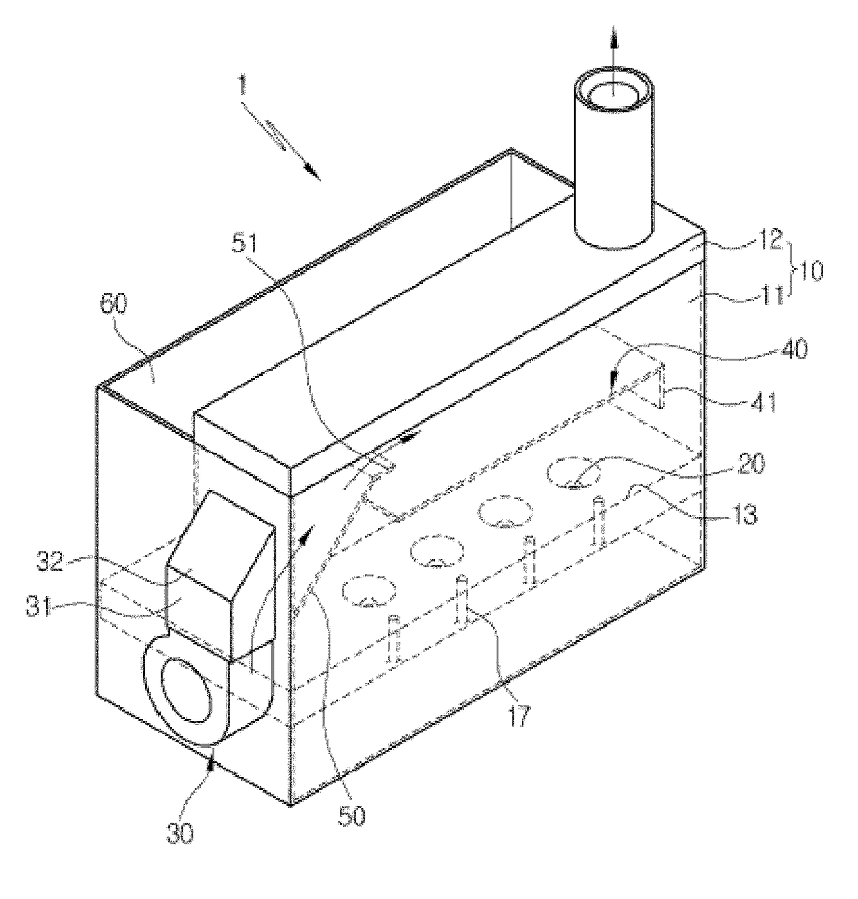
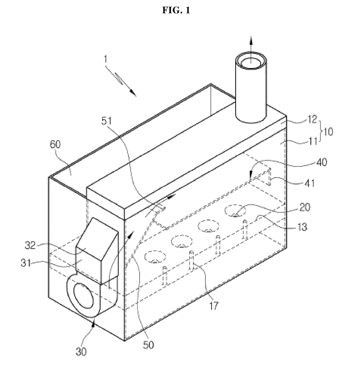
[0018]The super particle spraying apparatus 1 according to the present invention comprises a housing 10, an ultrasonic vibrator 20, a blower 30, an inner plate 40, and a spray nozzle 16.

[0019]The housing 10 comprises a body 11 in which a liquid is accommodated and an upper portion is opened and a lid 12 which is detachably coupled to an upper portion of the body 11 to close an opened upper portion of the body 11.

[0020]Since the liquid can use various liquids such as water or a liquid medicine, it can be used as a humidifier, a sterilizer, a sterilizer, and the like.

[0021]An air inlet 15 is formed at one side of the housing 10.

[0022]The air inlet 15 is formed on one side of the housing 10 facing the one longitudinal end portion of the inner plate 40 to be described later.

[0023]The housing 10 is provided with the fluid dispenser 16 so that fine liquid particles (5 μm or les...


PUM


Abstract

The present invention relates to a supraparticle atomizing device and, more specifically, to a supraparticle atomizing device having an inner plate provided at the upper part of an ultrasonic vibrator inside a housing and having a circulation passage formed at the circumference of the inner plate of the inside of the housing by using the rapid flow rate of the air to be ventilated to the inside of the housing through a blower, and thus only liquid microparticles generated at the lower region of the inner plate by the ultrasonic vibrator are pulled up to the upper region thereof, thereby allowing the liquid microparticles to be atomized through an atomizing hole and allowing the liquid microparticles to be rapidly diffused into the air with rapid ventilation air.

Description

TECHNICAL FIELD[0001]The present invention relates to a super-particle spraying apparatus, and more particularly, to a super-particle spraying apparatus in which an inner plate is provided on an upper side of an ultrasonic vibrator inside a housing, and a circulation passage is formed around the inner plate inside the housing by using fast stream velocity of air being blown into the housing through a blower, and a spray nozzle atomizing fine liquid particles which circulates from a lower area of the inner plate outside the housing through the circulation passage.BACKGROUND ART[0002]In general, a spraying apparatus using an ultrasonic vibrator is a device for spraying fine particles of water by ultrasonically vibrating the water, and has been mainly used for adjusting the humidity to keep the indoor condition pleasant by providing moisture in a dry place.[0003]As an example of the above-described spraying apparatus, Korean Patent Registration No. 10-0577241 briefly describes a sprayi...

Claims


Application Information

Patent Timeline
Patent Type & Authority Applications(United States)
IPC IPC(8): B05B17/06B05B1/02F24F6/12F24F13/08F24F13/20
CPCB05B17/0607B05B1/02F24F6/12F24F13/08F24F13/20F24F2013/205A61L2/22A61L9/14B05B17/06A61L2209/134A61L2202/15B05B7/0012B05B17/0615B05B17/0676F24F11/0008F24F2006/008
Inventor KIM, JEONG WOOKIM, JEONG YANGCHOI, YUN JAIE
Owner SEOUL NAT UNIV R&DB FOUND
Why Eureka
Try Eureka